System configuration, Hale foam proportioner system model – Hale 5.0 FoamLogix User Manual
Page 14
Ι−
8
Section
I
: Description
ROTARY GEAR PUMP
ELECTRONIC FOAM PROPORTIONING SYSTEM
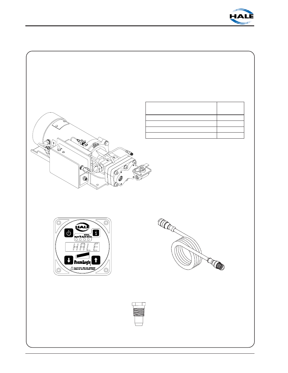
SYSTEM CONFIGURATION
Hale Foam Proportioner System Model
(Model 3.3 or Model 5.0)
All Hale Foam systems include: Foam Pump/Motor Assembly, Control Unit, Control Cable
and Check Valve/Injector Fitting
Foam Pump/Motor Assembly
(Shown with Bypass Valve when configured for MDT
ΙΙ
, MST or no tank selector option)
Control Unit
P/N 107064
Optional 6-Pin Extension Cable
16.5 Feet (P/N 013-2020-05-0)
6.5 Feet (P/N 013-2020-02-0)
Check Valve/Injector Fitting
P/N 038-1790-00-0
L
E
D
O
M
X
I
G
O
L
M
A
O
F
T
R
A
P
R
E
B
M
U
N
R
O
T
O
M
C
D
V
2
1
/
W
0
.
5
X
I
G
O
L
M
A
O
F
0
-
5
1
-
0
3
1
3
-
1
0
5
R
O
T
O
M
C
D
V
4
2
/
W
0
.
5
X
I
G
O
L
M
A
O
F
0
-
4
2
-
0
3
1
3
-
1
0
5
R
O
T
O
M
C
D
V
2
1
/
W
3
.
3
X
I
G
O
L
M
A
O
F
0
-
5
1
-
0
2
1
3
-
1
0
5
R
O
T
O
M
C
D
V
4
2
/
W
3
.
3
X
I
G
O
L
M
A
O
F
0
-
4
2
-
0
2
1
3
-
1
0
5
This manual is related to the following products: