Hale 5.0 FoamLogix User Manual
Page 69
ΙΙ
-39
ROTARY GEAR PUMP
ELECTRONIC FOAM PROPORTIONING SYSTEM
Section
II
: Installation
DUAL FOAM TANK SYSTEM
When the Hale FoamLogix system is installed
using a Hale ADT or Hale MDT
ΙΙ
connect
the low tank level sensors using the following
procedure (refer to figure 2-29):
CAUTION: Before running wires from the
low tank switches to the A-B switch box
make sure the wire from Tank A is
identified and properly labeled.
1. Using minimum 16 AWG Type SXL or
GXL (SAE J1128) wire, extend the pigtails
on the low tank level sensors to the A-B
switch box. When making splices to
extend the low tank sensor wires make
sure the splices are sealed using an
adhesive filled heat shrink tubing. Where
two wires exit the heat shrink tubing
pinch the tubing while heating the
tubing to make sure the adhesive seals
around both wires.
CAUTION: Use the silicone sealer
provided with the Hale FoamLogix
system to insulate the terminal strip
connection screws and prevent
corrosion.
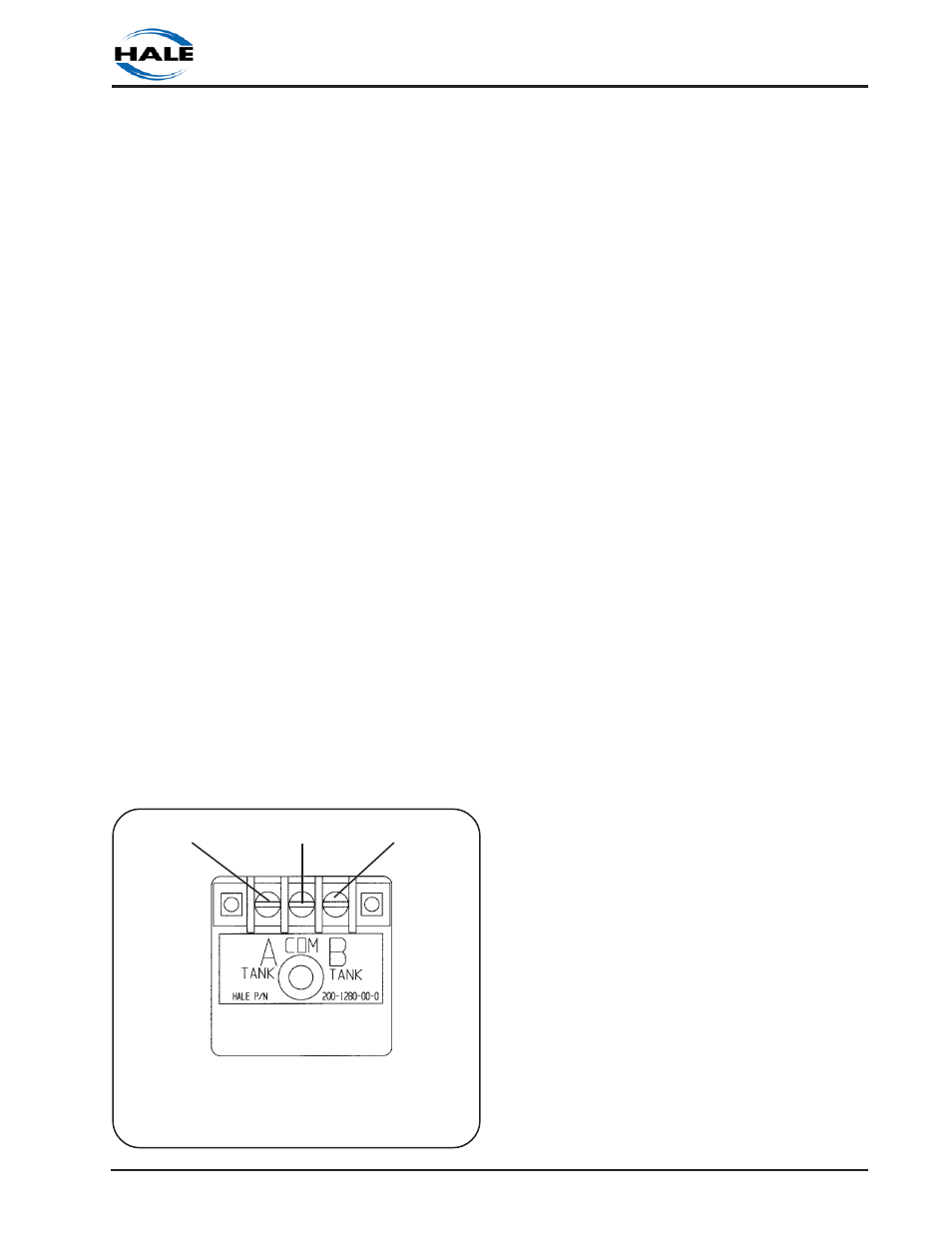
2. Tie one wire from each low level
switch together as a common lead.
Connect this common lead to the
center screw on the terminal block on
the A-B switch box.
3. Connect the lead from Tank A to the
terminal labeled A TANK on the switch
box and connect the wire from Tank B to
the terminal labeled B TANK.
4. Seal the terminal strip connections
using the silicone sealer provided.
DISPLAY UNIT POWER AND GROUND
CONNECTIONS
Power must be connected directly to
the display unit. The power and ground
connection is the 2 pin packard
connector on the 12 inches long pigtail
on the flow sensor harness (see figure 2-
24). The mating harness provided is
approximately 18 inches long. If
additional wire length is required, use
minimum 16 AWG type SXL, or GXL (SAE
J1128) wire.
Using the harness provided, connect the
black (B) wire to a chassis ground stud.
Protect the ground connection from
corrosion.
Connect the red (A) wire to the power
supply. Idealy this power wire should be
connected to a minimum 5 AMP fused
dedicated circuit. If a dedicated circuit
is not available then the power lead can
be connected to a terminal where there
is not a high current load. Acceptable
additional components powered from
this terminal include ENFO IV, Governor,
Tank Level Gauge, Etc.
DISTRIBUTION BOX GROUND AND
PRIMARY POWER CONNECTIONS
CAUTION: Connect the primary positive
lead from the terminal block to the
master switch terminal or relay terminal
using minimum 4 AWG type SGX (SAE
J1127) chemical resistant battery cable
and protect with wire loom.
CAUTION: Prevent corrosion of power
and ground connections by sealing
these connections with silicone sealant
Figure 2-29. Low Tank Sensor A-B
Switchbox Connections
TANK B
TERMINAL
COMMON
TERMINAL
TANK A
TERMINAL
A-B SWITCHBOX MOUNTED ON
FOAM PUMP