Hale 5.0 FoamLogix User Manual
Page 77
ΙΙ
-47
ROTARY GEAR PUMP
ELECTRONIC FOAM PROPORTIONING SYSTEM
Section
II
: Installation
2. If the system is equipped with ADT or
MDT
ΙΙ
move the selector to TANK B
position and observe the control unit
display. The display should alternate
between "
0
" and "
Lo b
" indicating the
foam tank is empty. Fill foam
concentrate tank B with water. The "
Lo
b
" indication should disappear from the
control unit display indicating the low
tank level sensor in Tank B is operating
properly.
3. If the system is equipped with ADT,
MDT
ΙΙ
or MST place the selector in the
FLUSH position. "
FLUSH
" should alternate
with "
0
" on the control unit display. Once
proper operation is verified place the
selector to TANK A position (or FOAM
TANK position on MST).
NOTE: The bypass valve on the ADT is a
pull to operate device. There are two
detents that the valve must pass through
to be fully open. Make sure the bypass
valve is fully opened before attempting
to operate foam pump.
4. Place the BYPASS valve to the
BYPASS position to check foam pump
operation. Place a calibrated five
gallon container at the discharge of the
bypass hose.
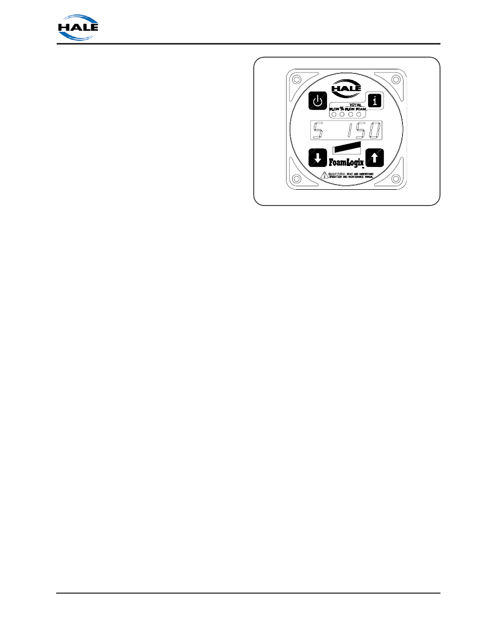
5. Place the system in simulated flow
mode by selecting the FLOW display and
depressing both up
é and down ê
buttons simultaneously. Set simulated
flow value to 100 GPM by pressing up
é
or down
ê button. Display will show “
S
”
at the left most position to indicate the
simulated flow (See figure 2-33).
6. Depress the SELECT DISPLAY button
until the LED under % FOAM lights. Set
foam concentrate injection rate to "
1.0
"
by pressing up
é or down ê button.
7. Depress the SELECT DISPLAY button
until the LED under TOTAL FOAM lights.
Figure 2-33. Simulated Flow Display
Depress ON button to energize Hale
FoamLogix system. Observe the
discharge of the bypass hose to make
sure the foam pump is operating. After
one minute depress the ON button to
stop the foam pump. There should be
approximately one gallon of water in
the container and the TOTAL FOAM
display on the control unit should read
approximately "
1.0
".
8. If the system is equipped with ADT or
MDT
ΙΙ
move the selector to TANK B
position and repeat steps 6 and 7 for
tank B.
9. After foam pump operation has
been checked with both foam tanks exit
simulated flow mode by selecting the
FLOW display and depressing both up
é
and down
ê buttons simultaneously.
10. Drain water from foam tanks and
concentrate lines and return the bypass
valve to the INJECT position.
11. Verify operation of and calibrate
flowsensor(s) as required using
flowsensor calibration procedures in the
user calibration section.
This completes the Hale FoamLogix system
operation checks that can be
accomplished at the system installer facility.
Foam pump feedback calibration along