Hale TPM Sistem User Manual
Hale Equipment
Hale Products Inc. • A Unit of IDEX Corporation • 700 Spring Mill Avenue • Conshohocken, PA 19428
Phone: 610/825-6300 • Fax: 610/825-6440 • 800-220-4253 • www.haleproducts.com
1
RETROFIT
If you are retrofitting the TPM System to an older pump, call the
Hale Pump Service Department, with the pump Serial Number to
verify that the pump has the proper openings for the TPM System
before attempting retrofit.
PMD CONTROL VALVE
Cut the mounting holes in the truck panel as shown on Plate
No. 742C. The new PMD Control Valve must be located higher
than the top of the midship pump to allow for proper drainage
.
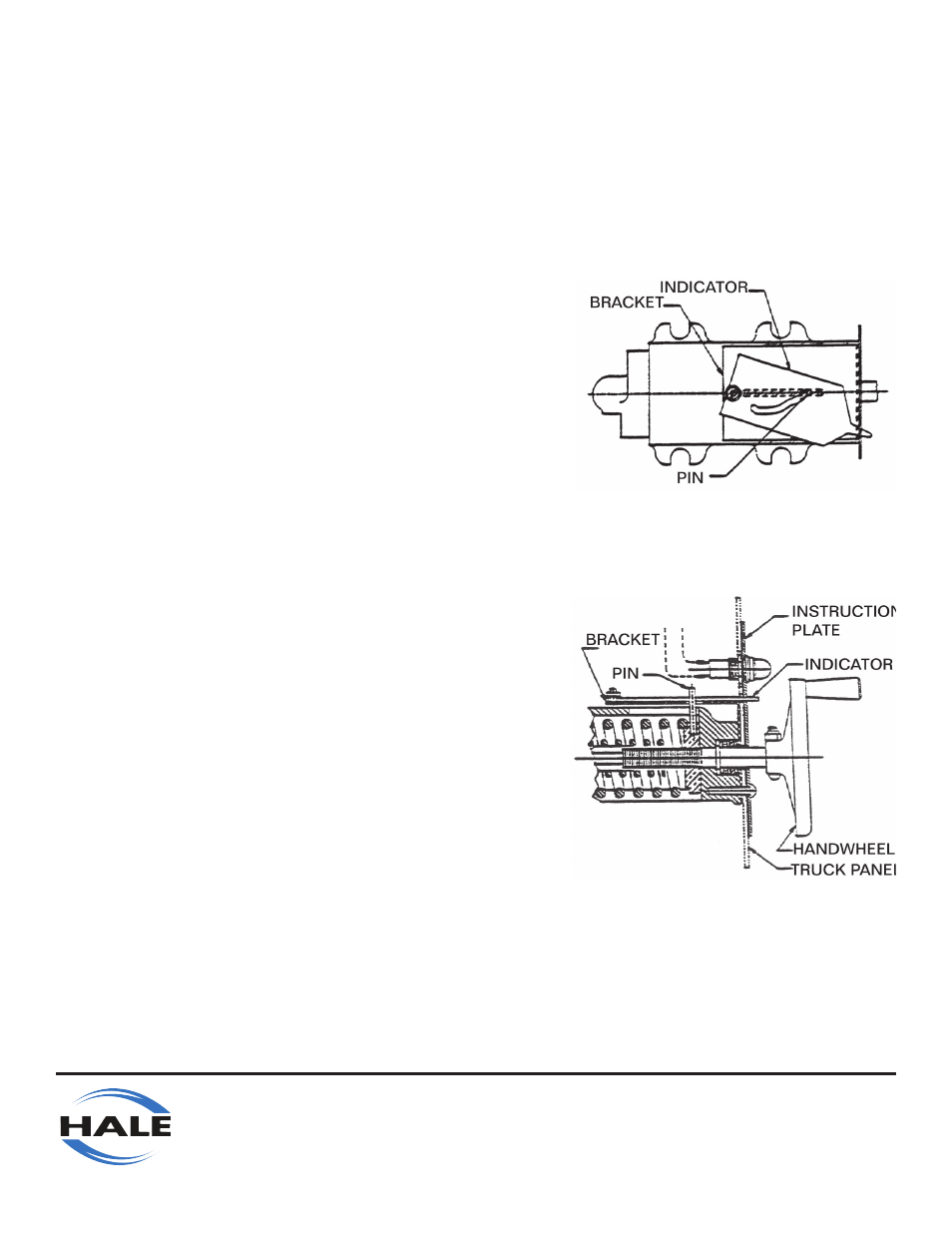
Install the indicator bracket assembly (519-0071-10-0) to the
PMD Control Valve by placing the slot in the bracket and
white pressure indicator over the pin in the PMD Control Valve.
The (4) mounting holes in the indicator bracket should align
with the tapped holes in the PMD Control Valve. The top view
of the PMD Control Valve with the indicator bracket assembly
installed is shown in Figure 1.
The PMD Control Valve assembly can now be mounted to the
truck panel as shown in Figure 2. The PMD Control Valve
Assembly is installed on the inside of the truck panel while the
instruction plate is on the outside. Attach the instruction plate to
the PMD Control Valve Assembly using the (4) 3/4-20 x 5/8 Lg.
Phillips Head Screws (018-1205-44-0). Tighten securely.
Attach the adjusting handwheel (512-0070-00=0) to the PMD
Control Valve Shaft using the screw (018-1214-45-0) and lock
nut (110-1205-11-0) provided. Turn the adjusting handwheel in
both directions to verify that the pressure indicator moves freely
to both extremes. If the pressure indicator does not move freely,
check for binding from the indicator lock nut (110-1008-06-0).
There should be approximately a 1/64-1/32 space between the
washer (097-0750-01-0) and the lock nut.
1.
2.
3.
4.
FIGURE 2
FIGURE 1
TPM SYSTEM INSTALLATION & OPERATION MANUAL
(Manual Part No. 101-0850-08-0)