Hale 5.0 FoamLogix User Manual
Page 64
ΙΙ
-34
ROTARY GEAR PUMP
ELECTRONIC FOAM PROPORTIONING SYSTEM
Section
II
: Installation
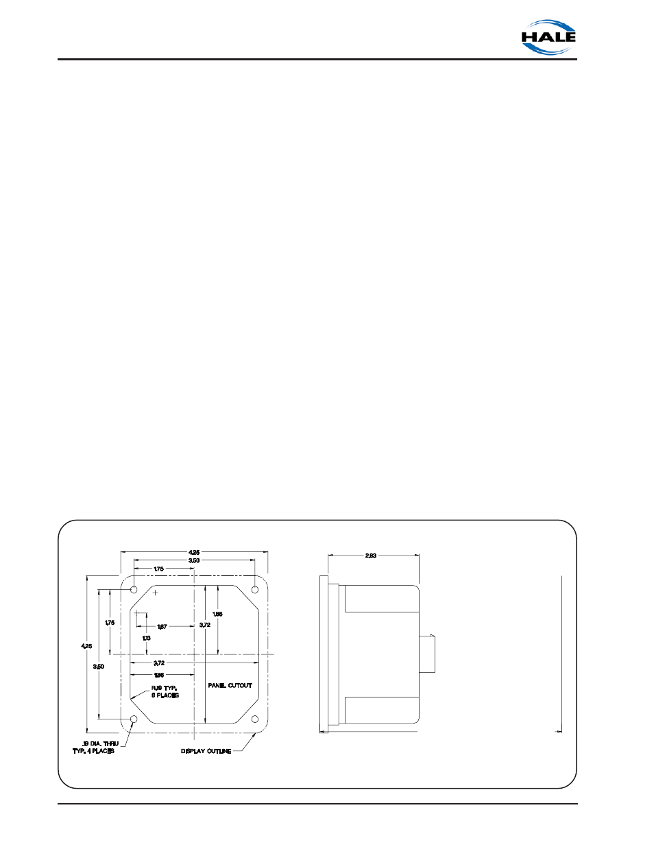
the four holes in the face (See figure 2-22 for
mounting dimensions). The display requires
7 inches (178 mm) minimum clearance from
the back of the operator panel to allow
proper connection of cables. Once the
control unit is mounted on the operator
panel, attach the 14 pin AMP connector on
the flow sensor cable assembly to the back
of the display. Referring to figures 2-23 and
2-24 make connections to the distribution
box and flow sensor.
NOTE: Ensure that the panel where the
control unit is mounted has an
adequate ground. For stainless steel
and vinyl coated panels a ground strap
½ inch (12 mm) wide must be attached
from one of the four screws holding the
control unit in place to the frame of the
fire truck to ensure adequate grounding.
FOAM TANK LOW LEVEL SENSOR
INSTALLATION
The foam tank low tank level sensor(s) must
be installed and wired to monitor foam
concentrate level. Mount a low tank level
sensor in each foam tank as follows. Refer
to figure 2-25 for low tank level sensor
mounting options.
CAUTION: Foam tank low level sensors
must be utilized to protect the Hale
FoamLogix from dry running. Failure to
use low level sensors with the Hale
FoamLogix system will void warranty.
SIDE MOUNT LOW LEVEL SENSOR
INSTALLATION
1. A side mount low tank level sensor is
available to be used if the bottom of the
foam tank is not accessible. The side mount
low tank level sensor has ½ inch NPT
threads. If tank design and construction
allows, the side mount sensor can be
threaded directly into the side of the tank at
the proper height. Also the sensor can be
mounted on the foam tank using a ½ x 1
inch NPT bushing and a bulkhead fitting
with 1 inch FNPT threads (see figure 2-26).
The center of the switch must be located at
least 1-½ to 2 inches (38 to 51 mm) from the
bottom of the foam tank with the float
positioned on top of the switch to move up
and down.
NOTE: When the side mount low tank
level sensor senses a low concentrate
condition the system will operate for one
minute unless the foam concentrate
level is restored. If the foam
Figure 2-22. Control Unit Mounting Dimensions
7.00 IN. (178 MM)
CLEARANCE BEHIND OPERATOR PANEL