Low level sensor wiring, Ιι -38, Fnpt x – Hale 5.0 FoamLogix User Manual
Page 68: Tube fitting and strain relief gland. attach the
ΙΙ
-38
ROTARY GEAR PUMP
ELECTRONIC FOAM PROPORTIONING SYSTEM
Section
II
: Installation
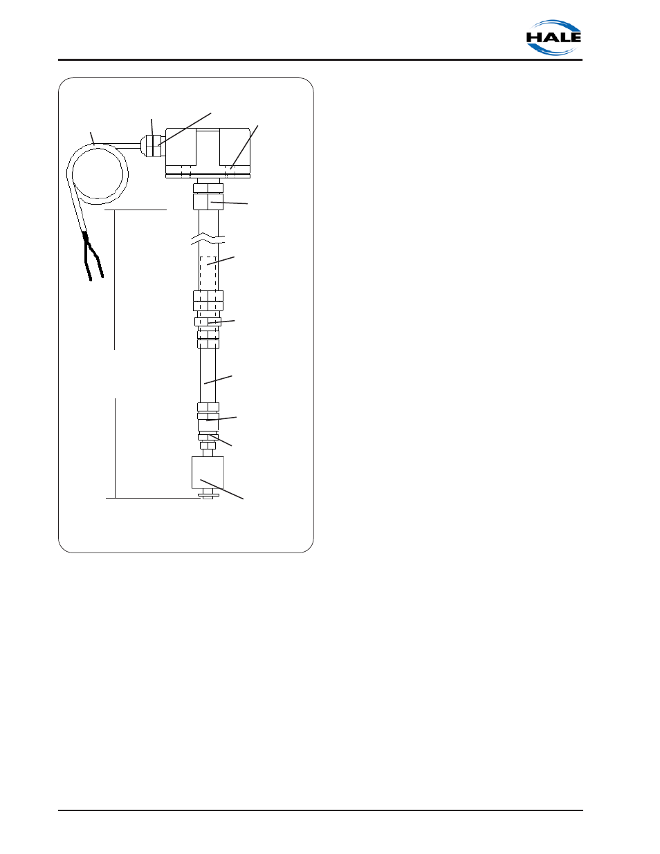
Figure 2-28. Top Mount Low Tank Switch
Assembly Component Identification
STRAIN
RELIEF
STRAIN RELIEF
GLAND NUT
FLANGE AND
GASKET
SENSOR
¼ NPT X
1
/
8
FNPT
BUSHING
¼ FNPT X ½ TUBE
FITTING
½ TUBE X
5
/
8
TUBE UNION
1
/
2
FNPT X
5
/
8
TUBE
FITTING
5
/
8
INCH O.D.
STAINLESS TUBE
½ INCH O.D.
STAINLESS TUBE
SENSOR
WIRE
3) Using a tubing cutter, remove the
required length of tube from the end of
each tube. Deburr the cuts when
complete.
4) Install a new ½ compression ferrule
on the end of the tube. Carefully thread
the sensor wire through the tube
assembly and attach the ¼ FNPT x ½
tube fitting with sensor attached to the
end of the tube. Tighten the ½ tube
compression nut.
5) Install a new
5
/
8
compression ferrule
on the end of the tube. Carefully thread
the sensor wire through the
3
/
8
FNPT x
5
/
8
tube fitting and strain relief gland.
Attach the
3
/
8
FNPT x
5
/
8
tube fitting and
strain relief to the end of the tube.
Tighten the
5
/
8
tube compression nut.
6) Slide the flange to the top of the 5/8
inch diameter tube and adjust the
telescoping section until the desired
length is achieved as measured from
the bottom of the flange to the bottom
of the sensor. Tighten the compression
fittings on the union to lock length.
CAUTION: When extending the low tank
sensor wires make sure the splices are
properly sealed using an adhesive filled
heat shrink tubing.
LOW LEVEL SENSOR WIRING
CAUTION: When extending the low tank
sensor wires make sure the splices are
properly sealed using an adhesive filled
heat shrink tubing.
SINGLE FOAM TANK SYSTEM
When a single foam tank system is installed
use minimum 16 AWG Type SXL or GXL (SAE
J1128) wire to extend the low tank sensor
wire to allow connection to the 2-wire
Packard WeatherPack connector on the
distribution box (see figure 2-23). Low tank
level sensors are not polarity sensitive
therefore terminal connections are not
specific.
If necessary, when making splices to extend
the low tank sensor wires make sure the
splices are sealed using an adhesive filled
heat shrink tubing. Where two wires exit the
heat shrink tubing pinch the tubing while
heating the tubing to make sure the
adhesive seals around both wires.
A connector kit (Hale P/N 546-1780-00-0) is
included that contains a Packard
WeatherPack 2-contact shroud half, two (2)
14-16 gage male terminals and two (2) 14-
16 gage cable seals. Assemble these
components to the end of the low tank
sensor wires. Snap the two halves of the
Packard WeatherPack connector together
making sure they are sealed.
MINIMUM LENGTH
WITHOUT CUTTING TUBE
SECTIONS 31-½ INCHES
(800 MM)