Don't, Figure 2-30. extra cable storage, Primary power supply connection – Hale 5.0 FoamLogix User Manual
Page 70: Table 2-1, Rfi/emi, Ιι -40
ΙΙ
-40
ROTARY GEAR PUMP
ELECTRONIC FOAM PROPORTIONING SYSTEM
Section
II
: Installation
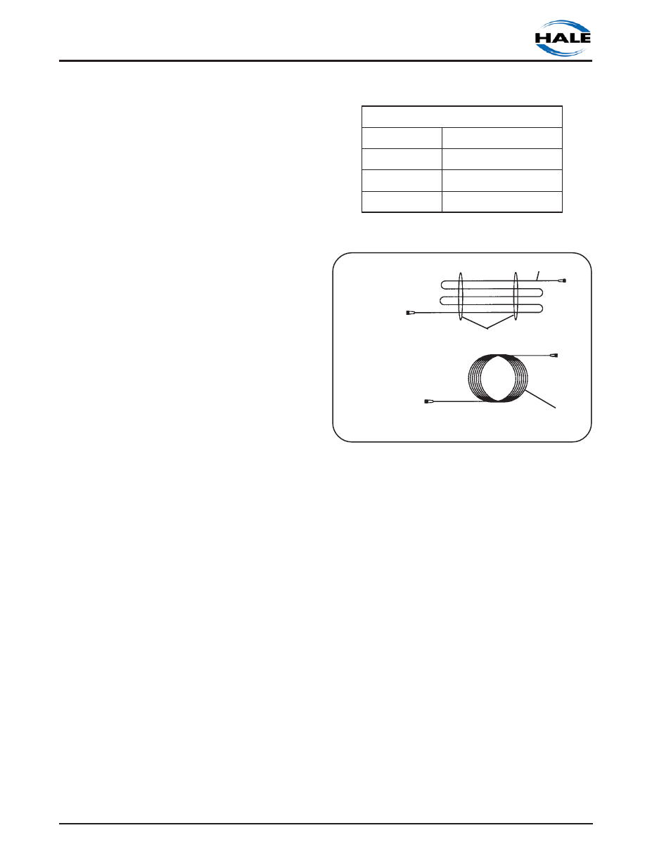
Figure 2-30. Extra Cable Storage
DON'T
MODULAR CABLE
MODULAR CABLE
DO
WIRE TIES
provided.
GROUND CONNECTION
Be sure the Hale FoamLogix system is
grounded to the chassis. Use a short length
of wide flat ground strap at least 1-¼ inches
(32 mm) wide and less than 18 inches (457
mm) long to reduce the potential of RFI
emitted by this connection. A stud labeled
NEG (—) is located on the distribution box to
attach the chassis ground strap to the Hale
FoamLogix system. (See figure 2-24) When
making the ground strap connections make
sure lugs are attached to the strap ends for
trouble free connections.
When the length of the ground strap
exceeds 18 inches (457 mm) use a wider
strap or a double thickness strap.
CAUTION: DO NOT connect the main
power lead to small leads that are
supplying some other device such as a
light bar or siren. The Hale FoamLogix
Model 3.3 and Model 5.0 require 60 AMP
minimum current. The Hale FoamLogix
Model 3.0 requires 40 AMP minimum
current.
PRIMARY POWER SUPPLY
CONNECTION
Make sure adequate switched electrical
power from the battery + terminal to the
battery connection stud on the distribution
box (see figure 2-24) is provided. Use 4
AWG minimum type SGX (SAE J1127)
battery cable directly to the battery,
battery switch or solenoids for cable runs up
to 6 feet (1.8 meters) long. Longer wire runs
may require larger battery cable for proper
operation. DO NOT connect power to the
same connection as the pump primer. The
following table provides recommended
cable size for various lengths of cable run.
Table 2-1
S
E
Z
I
S
E
L
B
A
C
R
E
W
O
P
Y
R
A
M
I
R
P
D
E
R
I
U
Q
E
R
0
.
5
&
3
.
3
s
l
e
d
o
M
h
t
g
n
e
L
m
u
m
i
x
a
M
m
m
(
G
W
A
4
2
)
s
s
e
L
r
o
)
M
8
.
1
(
t
F
6
m
m
(
G
W
A
0
2
)
)
M
6
.
4
(
t
F
5
1
o
t
)
M
8
.
1
(
t
F
6
m
m
(
G
W
A
0
0
2
)
r
e
g
n
o
L
r
o
)
M
6
.
4
(
t
F
5
1
RFI/EMI
Electrically shielded cables for control unit,
flowsensor, foam discharge multiplexing
display units and pressure transducers are
provided with the Hale FoamLogix system.
The cables are 100% electrically shielded to
eliminate the potential problem of EMI/RFI.
Proper installation of system components
and cables along with proper grounding will
limit radio interference caused by the Hale
FoamLogix system. Additionally, make sure
radio cables and hardware are not located
in the immediate area where Hale
FoamLogix equipment is mounted.
Make sure the flowsensor tee is grounded.
If metal piping is used sufficient grounding
may be present. However, Victaulic joints,
plastic pipe and rubber mounted pumps
interfere with proper grounding and an
additional ground strap may be required. If
necessary, connect a flat braided ground
strap at least ¼ inch (6 mm) wide from the
flowsensor tee to the apparatus frame to