Remote activation switch – Hale 5.0 FoamLogix User Manual
Page 71
ΙΙ
-41
ROTARY GEAR PUMP
ELECTRONIC FOAM PROPORTIONING SYSTEM
Section
II
: Installation
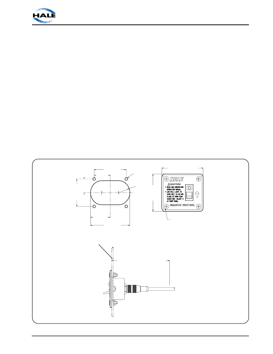
Figure 2-31. Remote Activation Switch Installation Dimensions
FOUR #10-32 UNC x 0.50 IN LG
MOUNTING SCREWS AND NUTS
FOUR 0.203 IN.
(5 MM) THRU
HOLES
0.88 IN.
(22 MM)
RADIUS
MOUNTING
PANEL
2.00 IN.
(51 MM)
1.00 IN.
(25 MM)
1.25 IN.
(32 MM)
2.50 IN.
(64 MM)
3.22 IN. (82 MM)
2.72 IN.
(69 MM)
3.06 IN.
(78 MM)
1.53 IN.
(39 MM)
4.50 IN. (114 MM) MINIMUM
CLEARANCE FOR CABLE
ensure proper grounding. The #6-32 UNC
screw that holds the spade terminal to the
flowsensor tee can be used to attach the
ground strap to the tee (refer to figure 2-11).
Making round coils of extra control and
flowsensor cables in the pump
compartment can act as an antenna.
While the control and flowsensor cables
cannot be shortened, various lengths of
cable are available to minimize the "extra"
cable in the truck. When routing control
and flowsensor cables take care to avoid
routing them next to antenna wires, radio
power lines and radio components. When
there is extra cable, double the cable back
on itself and secure with plastic wire ties in a
flat bundle instead of making a round coil.
(See Figure 2-30)
REMOTE ACTIVATION SWITCH
Choose a location in the apparatus
personnel compartment for mounting the
remote activation switch. Make sure the
switch is accessible to the operator without
interfering with other controls on the
apparatus.
To install the remote activation switch use
the following procedures (See Figure 2-31):
1. Determine location on panel where
switch is to be mounted. Refer to figure
2-33 and layout panel cutout and
mounting holes as shown.
2. Make panel cutout and drill the four
0.203 inch (5 mm) diameter thru holes.
3. Insert switch assembly through panel