Fs15 strainer fs25 strainer, Figure 2-14. fs series strainer orientation, Ιι -18 – Hale 5.0 FoamLogix User Manual
Page 48
ΙΙ
-18
ROTARY GEAR PUMP
ELECTRONIC FOAM PROPORTIONING SYSTEM
Section
II
: Installation
Figure 2-15. FS Series Strainer Mounting Dimensions
4.28 IN.
(109 MM)
3.00 IN.
(76 MM)
0.34 IN. (9 MM)
DIA. THRU HOLE
(4 PLACES)
1.00 IN.
(25 MM)
1.00 IN.
(25 MM)
1.50 IN.
(38 MM)
0.88 IN.
(22 MM)
1.13 IN.
(29 MM)
3.00 IN.
(76 MM)
1.50 IN.
(38 MM)
4.75 IN.
(121 MM)
2.38 IN.
(60 MM)
3.38 IN. (86 MM)
DIA. HOLE
7.09 IN.
(180 MM)
1 INCH NPT
THREADED
OUTLET
1 INCH
NPT
THREADED
INLET
2-½ INCH
NST CAP
¾ INCH NPT
THREADED
OUTLET
¾ INCH NPT
THREADED
INLET
1-½ INCH
NST CAP
7.34 IN.
(186 MM)
0.28 IN. (7 MM)
DIA. THRU HOLE
(4 PLACES)
2.13 IN. (54 MM)
DIA. HOLE
2.14 IN.
(54 MM)
4.28 IN.
(109 MM)
TYP.
OPERATOR
PANEL
OPERATOR
PANEL
FS15 STRAINER
FS25 STRAINER
inlet of the Hale MDT
ΙΙ
, Hale MST or
foam concentrate pump or correct
fitting on Hale ADT.
FS SERIES STRAINER
When a pressurized water flush is provided
to the strainer from one of the discharges
the use of Hale FS series strainers is required.
The plumbing exposed to the flush water
pressure must be rated at or above the
operating pressure of all other discharge
plumbing components. [500 PSI (34 BAR)
minimum]
The following procedures are provided for
installation of FS series strainers:
1. Choose a location on the apparatus
that allows gravity feed from the foam
tank to the strainer inlet and from the
strainer outlet to the foam pump suction
connection.
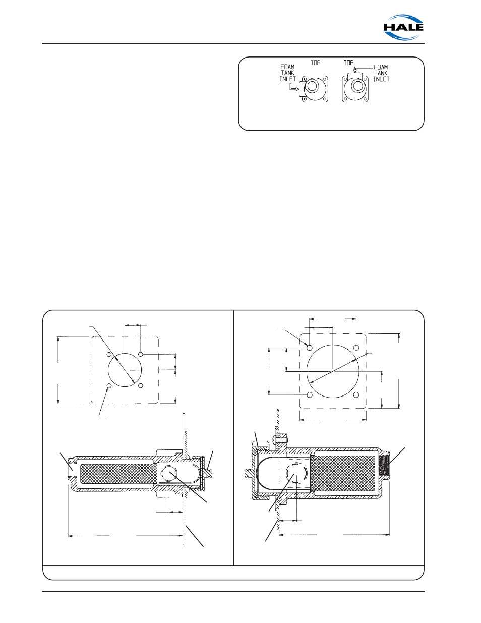
NOTE: When selecting the strainer
location make sure there is sufficient
space behind the pump panel to permit
attaching hoses and fittings. Make sure
the inlet connection port is oriented as
shown in figure 2-14 when installing the
FS series strainer.
2. Remove the strainer cap, mounting
screws and nameplate from the strainer
assembly.
3. Using the nameplate as a guide, or refer
to the diagrams in figure 2-15, mark
Figure 2-14. FS Series Strainer Orientation
LOOKING FROM BACK OF STRAINER