Correct incorrect – Hale 5.0 FoamLogix User Manual
Page 49
ΙΙ
-19
ROTARY GEAR PUMP
ELECTRONIC FOAM PROPORTIONING SYSTEM
Section
II
: Installation
holes for mounting the foam strainer.
The holes for the FS15 strainer mounting
screws are 9/32 inch (7 mm) and the
holes for FS25 strainer screws are 11/32
inch (9 mm) diameter. Additionally a
hole of sufficient size for the cap threads
to clear the panel is required. [FS15
strainer 2.13 inches (54 mm) and FS25
strainer 3.38 inches (86 mm)]
4. Select appropriate fittings for
attachment of the hoses to the strainer.
The fittings and hoses chosen must be
capable of withstanding the vacuum
generated by the foam pump [23
inches (584 mm) Hg] and the maximum
flushing water pressure [500 PSI (34
BAR)].
When using an FS15 strainer use ¾ inch
NPT x ¾ inch hose fittings.
When using an FS25 strainer use 1 inch
NPT x 1 inch hose fittings.
Before assembly coat all fitting threads
with a suitable thread sealant (Do not
use Teflon tape). Install the fittings into
the strainer and tighten securely.
5. Make sure the strainer is oriented as
shown in figure 2-14 and secure the
strainer body and nameplate to the
apparatus with the screws provided.
Install the cap on the strainer.
6. Install the hose from the foam tank
outlet to the inlet of the strainer. The
inlet of the strainer is closer to the
operator panel and is oriented as shown
in figure 2-14. Wetting the ends of the
hose and fittings will help ease
installation on the hose fittings.
CAUTION: Make sure the foam tank and
foam concentrate suction hoses are
clean before making final connection to
foam pump. Flush tank and hoses prior
to making connection.
7. Install the hose from the strainer outlet to
the inlet of the Hale FoamLogix foam
pump or selector valve.
CHECK VALVE/INJECTOR FITTING
The Hale check valve/injector fitting
supplied with the Hale FoamLogix system
meets NFPA requirements for a non-return
device in the foam injection system to
prevent back flow of water into the foam
concentrate tank. When properly installed
the brass and stainless steel construction
check valve/injector fitting ensures foam
concentrate is injected into the center of
the water flow for better mixing.
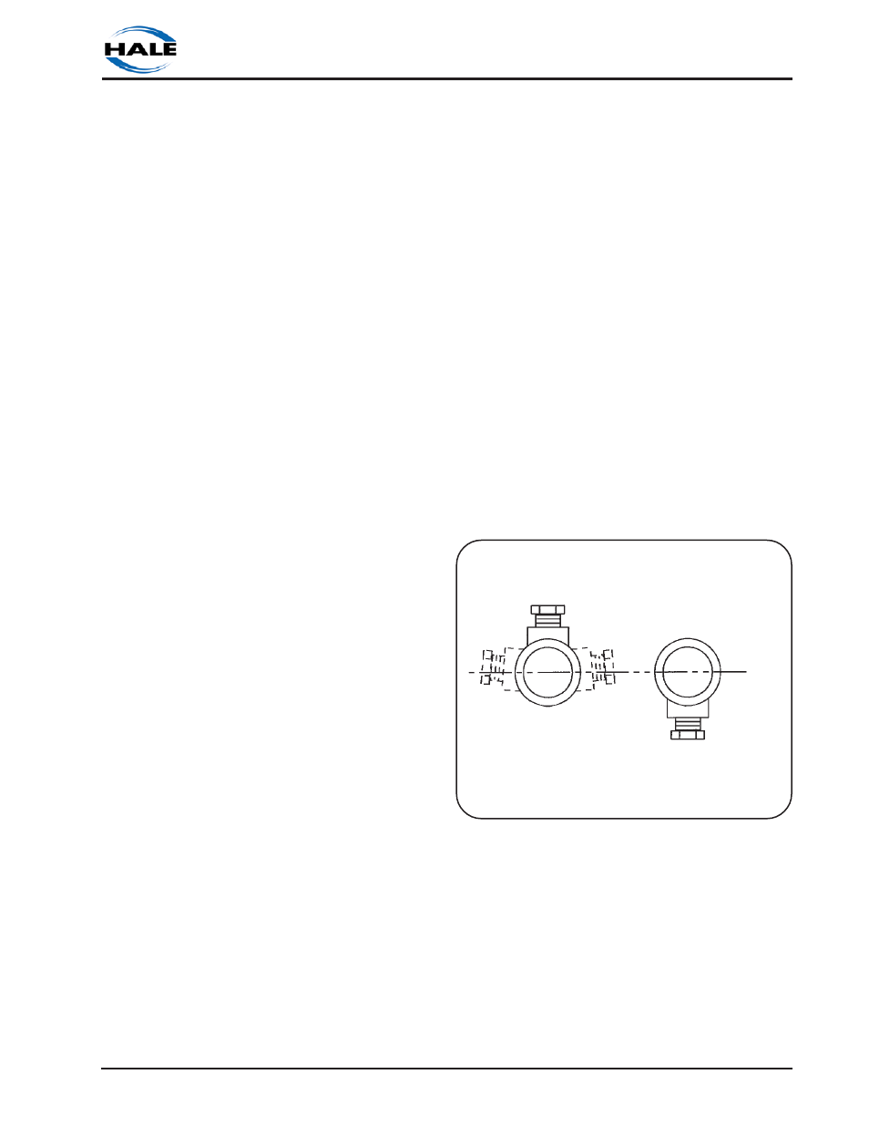
NOTE: Always position the check valve/
injector fitting at a horizontal or higher
angle to allow water to drain away from
the fitting (see figure 2-16). This will avoid
sediment deposits or the formation of an
ice plug.
The check valve/injector fitting MUST be
mounted in a location that is common to all
discharges which require foam concentrate
(see figure 2-18). The Hale FoamLogix
system does not permit a separate injection
point for each foam capable discharge.
The check valve/injector fitting has 1 inch
NPT threads on the outside to fit into the 1
CORRECT
INCORRECT
CHECK VALVE/INJECTOR FITTING
BELOW HORIZONTAL PLANE
Figure 2-16. Check Valve/Injector Fitting
Position
CHECK VALVE/INJECTOR FITTING
ABOVE HORIZONTAL PLANE