PLANET XGS3-24042 User Manual
Page 669
80-23
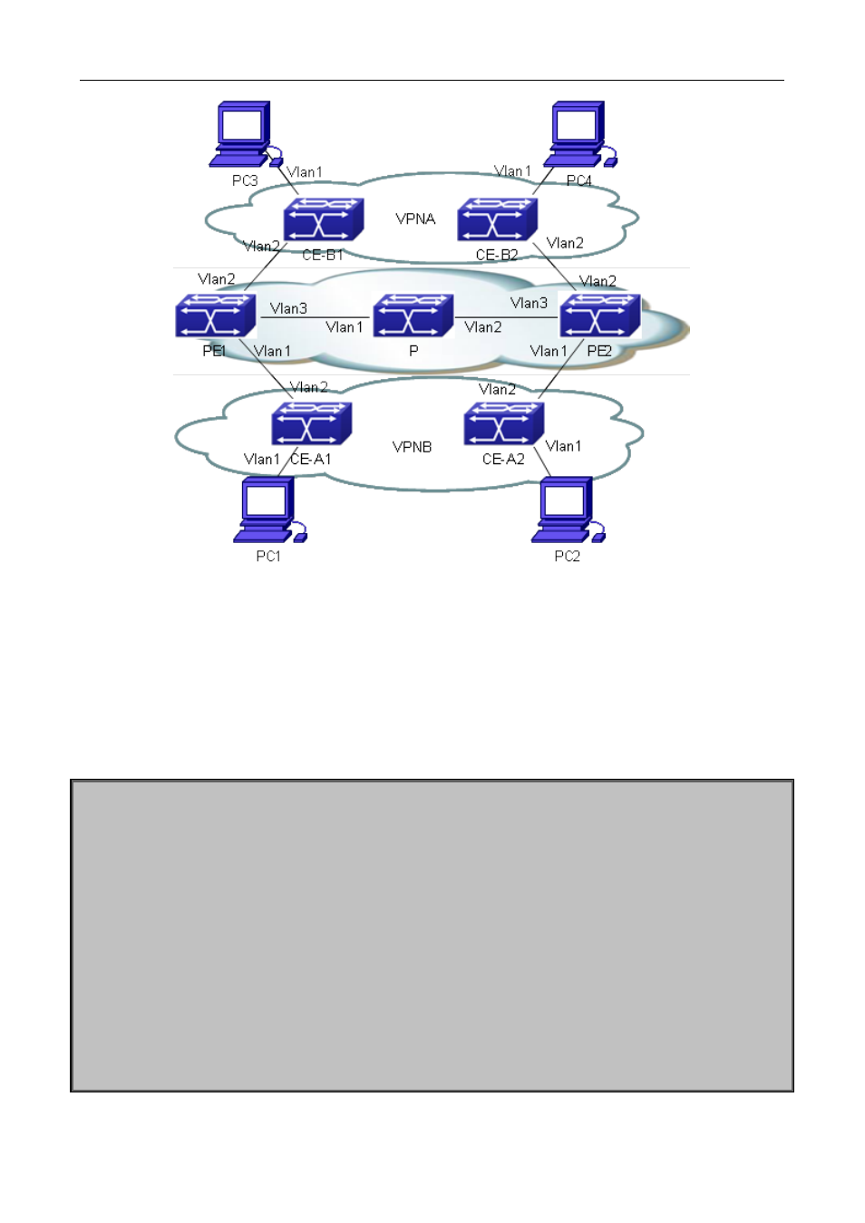
Figure 80-4 MPLS VPN Typical Instance
The above figure demonstrates a typical MPLS VPN instance, in which, PE1, P and PE2 form the public
network area – the area switching via MPLS. CE-A1 and CE-A2 form VPN-A, CE-B1 and CE-B2 form VPN-B.
Both VPNs communicate via the public network label switching, and need to configure LDP for distributing
and advertising labels in the public network area. To guarantee the reachability of routes, we advertise routes
via OSPF.
The LDP configuration of PE1 is as follows:
PE1#config
PE1(config)#mpls enable
PE1(config)# router ldp
PE1(config-router)#exit
PE1(config)#interface vlan 3
PE1(config-if-Vlan3)#ip address 202.200.1.2 255.255.255.0
PE1(config-if-Vlan3)#ldp enable
PE1(config-if-Vlan3)#label-switching
PE1(config-if-Vlan3)#exit
PE1(config)#router ospf
PE1(config-router)#network 200.200.1.1/32 area 0
PE1(config-router)#network 202.200.1.0/24 area 0
PE1(config-router)#exit