PLANET XGS3-24042 User Manual
Page 455
48-54
The configuration steps are listed below:
Switch#config
Switch(config)#ip igmp proxy
Switch(Config)#interface vlan 1
Switch(Config-if-Vlan1)#ip igmp proxy upstream
Switch(Config)#interface vlan 2
Switch(Config-if-Vlan2)#ip igmp proxy downstream
Multicast Configuration:
Suppose the multicast server offers some programs through 224.1.1.1. Some hosts subscribe that program at
the edge of the network. The IGMP multicast members report themselves to the downstream ports of IGMP
Proxy enabled Switch 2 and Switch 3. Switch 2 and Switch 3 then aggregate the group membership
information and send them through the upstream ports. Switch 1 finally forward these membership
information to the multicast router when receiving the group membership information through upstream ports,
and deliver the multicast dataflow through downstream ports.
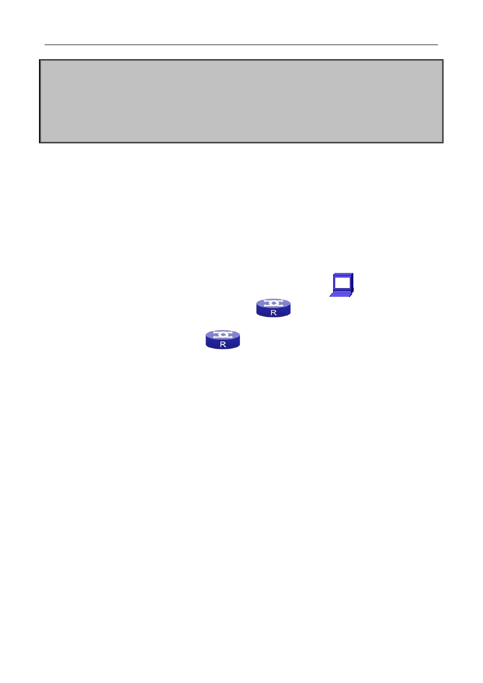
Example2: IGMP Proxy for multicast sources from downstream ports.
Figure
48-13
IGMP Proxy for multicast sources from downstream ports
As it is show in the figure above, IGMP Proxy enabled switches connected to the network in tree topology. The
multicast source server connects to the downstream port of Switch1, the multicast dataflow is distributed
through the upstream port and other downstream ports. Three IGMP Proxy enabled switches which are
connected in tree topology, respectively have one port connected to multicast routers, and no less than one
ports connected to hosts or upstream ports from other IGMP proxy enabled switches.
The configuration steps are listed below:
IGMP PROXY Switch1 configuration:
Multicast
Server
Multicast
Router
IGMP PROXY
Switch 2
IGMP PROXY
Switch 1
IGMP PROXY
Switch 3
Multicast
Router