KEPCO MBT Series User Manual
Operator’s manual, Kepco, Mbt series
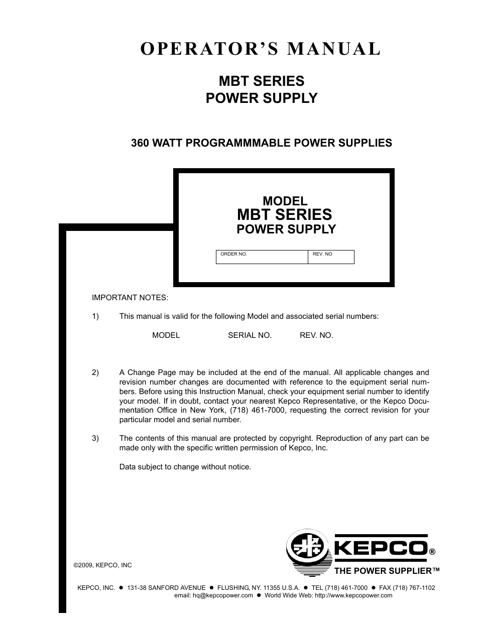
Table of contents
Document Outline
- SECTION 1 - INTRODUCTION
- SECTION 2 - INSTALLATION
- SECTION 3 - OPERATION
- SECTION 4 - THEORY OF OPERATION
- SECTION 1 - INTRODUCTION
- 1.1 Scope of Manual
- 1.2 General Description
- 1.3 Specifications
- TABLE 1-1. Model Parameters
- TABLE 1-2. General Specifications
- FIGURE 1-2. MBT Series Power Supply, Mechanical Outline Drawing
- 1.4 Features
- 1.4.1 Local Control
- 1.4.2 Remote Control
- 1.5 Options
- 1.5.1 Option G - Single Board Computer
- 1.5.2 Option R - Output/Polarity Reversal Relays
- FIGURE 1-3. Remotely Controlled Power Supply Configurations Using Kepco Products
- 1.6 Equipment Supplied
- TABLE 1-3. Equipment Supplied
- 1.7 Accessories
- TABLE 1-4. Accessories
- SECTION 2 - INSTALLATION
- 2.1 Unpacking and Inspection
- 2.2 Terminations and Controls
- 2.3 Source Power Requirements
- 2.4 Cooling
- FIGURE 2-1. MBT Series Front Panel Controls and Indicators
- FIGURE 2-2. MBT Series Internal Controls Accessible Through Top Cover
- TABLE 2-1. Internal Controls Accessible Through Top Cover
- TABLE 2-2. Input/Output Pin Assignments for Remote Control
- FIGURE 2-3. MBT Series Rear Panel Connections
- FIGURE 2-4. Connector Pin Assignments
- 2.5 Preliminary Operating Procedures
- 2.5.1 Node Address (Channel Number) Selection
- TABLE 2-3. Node Address Selection
- 2.5.2 Preliminary Operational Check
- 2.6 Installation
- 2.6.1 Bench Top Use
- 2.6.2 Rack Mounting
- 2.6.3 “G” Option Selector (MG and MGR Models)
- 2.7 Wiring Instructions
- 2.7.1 Safety Grounding
- 2.7.2 Source Power Connections
- 2.7.3 D-C Output Grounding
- 2.7.4 Power Supply/Load Interface
- 2.7.5 Load Connection - General
- 2.7.6 Load Connection Using Local Sensing
- 2.7.7 Load Connection Using Remote Sensing
- 2.8 Operating Configuration
- TABLE 2-4. Internal Jumper Configuration
- 2.9 RS 232 Connections
- FIGURE 2-5. Grounded Load Connections, Local Sensing
- FIGURE 2-6. Isolated Load Connections, Local Sensing
- FIGURE 2-7. Grounded Load Connections, Remote Sensing
- FIGURE 2-8. Isolated Load Connections, Remote Sensing
- SECTION 3 - OPERATION
- 3.1 General
- 3.1.1 Actual Mode
- 3.1.2 Commanded Mode
- 3.1.3 Local Mode
- 3.1.4 Remote Mode
- 3.2 Local Mode Operation
- 3.2.1 Local Mode Controls and Indicators
- 3.2.1.1 Front Panel Controls and Indicators.
- TABLE 3-1. Front Panel Controls And Indicators
- TABLE 3-2. Key Functions
- 3.2.1.2 Keypad Operation
- 3.2.1.3 Turning the Power Supply On
- 3.2.1.4 Setting Local Mode
- 3.2.1.5 Enabling/Disabling DC Output Power
- 3.2.1.5.1 M and MG Models
- 3.2.1.5.2 MR and MGR Models
- 3.2.1.6 Setting Output Voltage or Voltage Limit
- 3.2.1.6.1 Using Vadj and Numeric Keys — M, MG Models
- TABLE 3-3. Using Vadj and Keypad Entries To Set Output Voltage/Voltage Limit — Models M, MG
- 3.2.1.6.2 Using Vadj and Numeric Keys — MR, MGR Models
- TABLE 3-4. Using Vadj and Keypad Entries To Set Output Voltage/Voltage Limit — Models MR, MGR
- 3.2.1.6.3 Procedure Using Vadj and Numeric Keypad
- 3.2.1.6.4 Slew (s and t) Keys — M, MG Models
- TABLE 3-5. Using Slew Keys (s and t) to Set Output Voltage/Voltage Limit — Models M, MG
- 3.2.1.6.5 Slew (s and t) Keys — MR, MGR Models
- TABLE 3-6. Using Slew Keys (s and t) to Set Output Voltage/Voltage Limit — Models MR, MGR
- 3.2.1.6.6 Voltage Control — M, MG Models
- TABLE 3-7. Using Voltage Control to Set Output Voltage/Voltage Limit — Models M, MG
- 3.2.1.6.7 Voltage Control — MR, MGR Models
- TABLE 3-8. Using Voltage Control To Set Output Voltage/Voltage Limit — Models MR, MGR
- 3.2.1.7 Setting Output Current or Current Limit
- 3.2.1.7.1 Using Iadj and Numeric Keys — M, MG Models
- TABLE 3-9. Using Iadj and Keypad Entries to Set Output Current/Current Limit — Models M, MG
- 3.2.1.7.2 Using Iadj and Numeric Keys — MR, MGR Models
- TABLE 3-10. Using Iadj and Keypad Entries To Set Output Current/Current Limit — Models MR, MGR
- 3.2.1.7.3 Procedure Using Iadj and Numeric Keypad
- 3.2.1.7.4 Slew (s and t) Keys — M, MG Models
- TABLE 3-11. Using Slew Keys (s and t) to Set Output Current/Current Limit — Models M, MG
- 3.2.1.7.5 Slew (s and t) Keys — MR, MGR Models
- TABLE 3-12. Using Slew Keys (s and t) to Set Output Current/Current Limit — Models MR, MGR
- 3.2.1.7.6 Current Control — M, MG Models
- TABLE 3-13. Using Current Control To Set Output Current/Current Limit — Models M, MG
- 3.2.1.7.7 Current Control — MR, MGR Models
- TABLE 3-14. Using Current Control to Set Output Current/Current Limit — Models MR, MGR
- 3.2.1.8 Setting Voltage Mode or Current Mode
- 3.2.1.8.1 M, MG Models
- 3.2.1.8.2 MR, MGR Models
- 3.2.1.9 Reversing DC Output Polarity — MR, MGR Models
- 3.2.1.10 Changing the GPIB Address
- 3.2.1.11 Local Mode Programming of the Power Supply
- TABLE 3-15. Programming Mode Screens
- 3.2.1.11.1 Entering Program Mode
- 3.2.1.11.2 Creating a New Program
- TABLE 3-16. Default Parameters for New Added Steps
- TABLE 3-17. Sample Program (Assigned Program #2)
- 3.2.1.11.3 Running a Program
- 3.2.1.11.4 Modifying a Program
- 3.2.1.11.5 Cycling a Program
- 3.2.1.11.6 Stopping a Program
- 3.2.1.11.7 Exiting Program Mode
- 3.2.1.11.8 Sample Program Operation - Models M, MG
- FIGURE 3-1. Sample Program Operation for M, MG Models
- FIGURE 3-2. Sample Program Operation for MR, MGR Models
- 3.2.2 Using the Menu System
- TABLE 3-18. Menu Functions
- 3.2.2.1 Speaker On/Off
- 3.2.2.2 Controls Lock-out
- 3.2.2.3 Remote Channel
- 3.2.2.3.1 General Notes for Remote Configurations Using IEEE 1118 Bus
- 3.2.2.3.2 Remote Operation Using Keypad to Control Another MBT Power Supply
- 3.2.2.4 Calibration
- 3.2.2.5 OVP, OCP Set-up
- 3.2.2.6 Slew Key Increments Set-up
- 3.2.2.7 Remote Display Blanking
- 3.2.2.8 GPIB Addressing Mode
- 3.2.2.9 Compatiblity Mode
- TABLE 3-19. MBT-G Compatibility Modes
- 3.2.2.10 Command Language
- 3.3 Remote Mode Programming
- 3.3.1 General
- 3.3.2 IEEE 488 (GPIB) Bus Protocol
- TABLE 3-20. IEEE 488 (GPIB) Bus Interface Functions
- 3.3.2.1 String Parsing
- TABLE 3-21. IEEE 488 (GPIB) Bus Command Mode Messages
- TABLE 3-22. IEEE 488 (GPIB) Bus Data Mode Messages
- 3.3.3 RS232-C Bus Protocol
- 3.3.3.1 RS 232 Implementation
- FIGURE 3-3. RS 232 Implementation
- 3.3.3.2 Echo Mode
- 3.3.3.3 Prompt Method
- 3.3.3.4 XON XOFF Method
- 3.3.3.5 Special Commands
- TABLE 3-23. XON XOFF Control
- 3.3.4 Programming Techniques to Optimize Power Supply performance
- 3.3.5 SCPI Programming
- 3.3.5.1 SCPI Messages
- 3.3.5.2 Common Commands/Queries
- 3.3.5.3 SCPI Subsystem Command/Query Structure
- TABLE 3-24. SCPI Command Index
- FIGURE 3-4. Tree Diagram of SCPI Commands Used with MBT-G Power Supplies
- 3.3.5.4 Program Message Structure
- FIGURE 3-5. Message Structure
- 3.3.5.4.1 Keyword
- TABLE 3-25. Rules Governing Shortform Keywords
- 3.3.5.4.2 Keyword Separator
- 3.3.5.4.3 Query Indicator
- 3.3.5.4.4 Data
- 3.3.5.4.5 Data Separator
- 3.3.5.4.6 Message Unit Separator
- 3.3.5.4.7 Root Specifier
- 3.3.5.4.8 Message Terminator
- 3.3.5.5 Understanding The Command Structure
- 3.3.5.6 Addressing Multiple Power Supplies
- 3.3.5.7 Understanding The Command Structure
- 3.3.5.8 Program Message Syntax Summary
- 3.3.5.9 Status Reporting
- 3.3.5.9.1 STATUS REPORTING STRUCTURE
- 3.3.5.9.2 Operational Status Register
- 3.3.5.9.3 QUEStionable Status Register
- FIGURE 3-6. Status Reporting Structure
- 3.3.5.9.4 Multiple Logical Instruments
- FIGURE 3-7. Expansion of QUEStionable Register for Multiple Logical Instruments
- 3.3.5.10 SCPI Program Example
- FIGURE 3-8. Typical Example Of MBT-G Power Supply Program Using SCPI Commands
- 3.3.6 CIIL Programming
- SECTION 4 - THEORY OF OPERATION
- 4.1 Introduction
- FIGURE 4-1. Crossover Characteristics of the MBT Power Supply Showing the Critical or Crossover Value of Load Resistance Rlx
- 4.1.1 Voltage Source.
- 4.1.2 Current Source
- 4.1.3 Voltage Mode
- FIGURE 4-2. Voltage Comparison Equivalent Circuit
- 4.1.4 Current Mode
- FIGURE 4-3. Current Comparison Equivalent Circuit
- 4.1.5 Voltage/Current Reference
- 4.1.6 A/D Conversion
- 4.1.7 Voltage/Current Comparison Errors
- 4.1.8 Protective Circuits
- 4.1.8.1 Overvoltage/Overcurrent Protection
- 4.1.8.2 Overtemperature Protection
- 4.1.8.3 Power Loss Protection
- 4.1.8.4 Path Fault Protection
- 4.1.8.5 Crowbar and Turn-off Circuit
- 4.1.9 Response Time
- 4.1.10 Retention of Programmed Values
- 4.1.11 Output Enable/Disable and Polarity Reversal Relays — MR, MGR Models
- 4.1.12 Output Enable/Disable
- 4.1.12.1 M, MG Models
- 4.1.12.2 MR, MGR Models
- 4.1.13 Local Control
- 4.1.13.1 Set Output Voltage/Current Limit (Voltage Mode)
- 4.1.13.2 Set Output Current/Voltage Limit (Current Mode)
- 4.1.13.3 Set Voltage/Current Mode
- 4.1.13.4 Output Enable/Disable
- 4.1.13.5 Programmable Parameters
- 4.1.13.6 Status
- 4.1.13.7 Menu-selectable Parameters
- 4.1.14 Remote Control
- 4.2 MBT Series Block Diagram Circuit Description
- FIGURE 4-4. MBT Series Power Supply, Overall Block Diagram
- 4.3 Detailed Circuit Descriptions
- FIGURE 4-5. MBT Series Power Supply, Location of Major Components
- 4.3.1 Analog Control Board A1
- 4.3.2 Relay and Flags Board A2
- 4.3.3 Digital Control Board A3
- 4.3.4 Auxiliary Supply Board A4
- 4.3.5 Mother Board A5
- 4.3.6 A-C Input Circuit and Main D-C Supply (Chassis A6)
- 4.3.7 Heat Sink Assembly A7
- 4.3.8 Front Panel Board A8
- 4.3.9 Sensing Resistor and Crowbar Circuit A10
- 4.3.10 Alphanumeric Display (LCD) A11
- 4.3.11 Keypad A12
- 4.3.12 "G" Option Components — MG, MGR Models
- 4.3.12.1 Single Board Computer (SBC) A13 — MG, MGR Models
- 4.3.12.2 Interface Board A14 — MG, MGR Models
- 4.3.13 "R" Option Components — MR, MGR Models
- APPENDIX A - SCPI COMMON COMMAND/QUERY DEFINITIONS
- A.1 Introduction
- TABLE A-1. IEEE 488.2 Command/query Index
- A.2 *CLS — Clear Status Command
- A.3 *ESE — Standard Event Status Enable Command
- TABLE A-2. Standard Event Status Enable Register and Standard Event Status Register Bits
- A.4 *ESE? — Standard Event Status Enable Query
- A.5 *ESR? — Event Status Register Query
- A.6 *IDN? — Identification Query
- A.7 *OPC — Operation Complete Command
- FIGURE A-1. GPIB Commands
- A.8 *OPC? — Operation Complete Query
- A.9 *OPT? — Options Query
- A.10 *RST — Reset Command
- A.11 *SRE — Service Request Enable Command
- TABLE A-3. Service Request Enable and Status Byte Register Bits
- A.12 *SRE? — Service Request Enable Query
- A.13 *STB? — Status Byte Register Query
- A.14 *TRG — Trigger Command
- A.15 *TST? — Self Test Query
- A.16 *WAI — Wait-to-Continue Command
- FIGURE A-2. Using the *WAIt-to-continue Command
- APPENDIX B - SCPI COMMAND/QUERY DEFINITIONS
- B.1 Introduction
- TABLE B-1. SCPI Subsystem Command/query Index
- B.2 INITiate[:IMMediate] Command
- B.3 INITiate:CONTinuous Command
- B.4 INITiate:CONTinuous? Query
- B.5 INSTrument:CATalog? Query
- FIGURE B-1. Use of INSTrument:CATalog Query
- B.6 INSTrument[:NSELect] Command
- B.7 INSTrument[:SELect] Command
- B.8 INSTrument[:SELect]? Query
- B.9 INSTrument:STATe Command
- FIGURE B-2. Identifying and Selecting Devices on BITBUS
- B.10 MEASure[:SCALar]:CURRent[:DC]? Query
- B.11 MEASure[:SCALar][:VOLTage][:DC]? Query
- B.12 OUTPut[:STATe] Command
- B.13 OUTPut[:STATe] Query
- B.14 [SOURce:]CURRent[:LEVel][:IMMediate][:AMPlitude] Command
- B.15 [SOURce:]CURRent[:LEVel][:IMMediate][:AMPlitude]? Query
- FIGURE B-3. Programming the Output
- B.16 [SOURce:]CURRent:[:LEVel]TRIGgered[:AMPlitude] Command
- B.17 [SOURce:]CURRent:[:LEVel]TRIGgered[:AMPlitude]? Query
- FIGURE B-4. Programming Current
- B.18 [SOURce:]VOLTage[:LEVel][:IMMediate][:AMPlitude] Command
- B.19 [SOURce:]VOLTage[:LEVel][:IMMediate][:AMPlitude]? Query
- B.20 [SOURce:]VOLTage:[:LEVel]TRIGgered[:AMPlitude] Command
- B.21 [SOURce:]VOLTage:[:LEVel]TRIGgered[:AMPlitude]? Query
- B.22 [SOURce:]FUNCtion:MODE Command
- B.23 STATus:OPERation:CONDition? Query
- TABLE B-2. Operation Condition Register, Operation Enable Register, and Operation Event Register Bits
- B.24 STATus:OPERation:ENABle Command
- B.25 STATus:OPERation:ENABle? Query
- B.26 STATus:OPERation[:EVENt]? Query
- B.27 STATus:PRESet Command
- FIGURE B-5. Using Status Commands and Queries
- B.28 STATus:QUEStionable[:EVENt]? Query
- B.29 STATus:QUEStionable:CONDition? Query
- TABLE B-3. Questionable Event Register, Questionable Condition Register and Questionable Condition Enable Register Bits
- B.30 STATus:QUEStionable:ENABle Command
- B.31 STATus:QUEStionable:ENABle? Query
- B.32 STATus:QUEStionable:INSTrument? Query
- TABLE B-4. Questionable Instrument Register 0 Bits
- B.33 STATus:QUEStionable:INSTrument1? Query
- TABLE B-5. Questionable Instrument Register 1 Bits
- B.34 STATus:QUEStionable:INSTrument2? Query
- TABLE B-6. Questionable Instrument Register 2 Bits
- B.35 STATus:QUEStionable:INSTrument:ENABle Command
- B.36 STATus:QUEStionable:INSTrument:ENABle? Query
- B.37 STATus:QUEStionable:INSTrument1:ENABle Command
- B.38 STATus:QUEStionable:INSTrument1:ENABle? Query
- B.39 STATus:QUEStionable:INSTrument2:ENABle Command
- B.40 STATus:QUEStionable:INSTrument2:ENABle? Query
- B.41 STATus:QUEStionable:INSTrument:ISUM? Query
- B.42 STATus:QUEStionable:INSTrument:ISUM:ENABle Command
- B.43 STATus:QUEStionable:INSTrument:ISUM:ENABle? Query
- B.44 SYSTem:COMMunication:GPIB:ADDRess Command
- B.45 SYSTem:COMMunication:SERial:BAUD Command
- B.46 SYSTem:COMMunication:SERial:ECHO Command
- B.47 SYSTem:COMMunication:SERial:PACE Command
- B.48 SYSTem:COMMunication:SERial::PROMpt Command
- B.49 SYSTem:ERRor[:NEXT]? Query
- B.50 SYSTem:ERRor:CODE? Query
- B.51 SYSTem:ERRor:CODE:ALL? Query
- B.52 SYSTem:LANGuage Command
- TABLE B-7. Error Messages
- B.53 SYSTem:SET Command
- B.54 SYSTem:VERSion Query
- APPENDIX C - CIIL COMMAND DEFINITIONS
- TABLE C-1. CIIL Subsystem Command/query Index
- FIGURE C-1. FNC — Function Command
- FIGURE C-2. INX — Initiate Op Code Command
- FIGURE C-3. FTH — Fetch Command
- FIGURE C-4. SET Command
- FIGURE C-5. OPN, CLS — Open, Close Relay Commands
- FIGURE C-6. RST — Reset Command
- FIGURE C-7. CNF, IST — Confidence Test, Internal Self Test Commands
- TABLE C-2. CIIL Error Messages
- FIGURE C-8. STA — Status Command
- TABLE C-3. CIIL Error Handling Utility Commands
- FIGURE C-9. GAL — Go to Alternate Language Command