Section 4 - theory of operation, 1 introduction, 1 voltage source – KEPCO MBT Series User Manual
Page 107: Introduction -1, Voltage source -1
MBTSVC111609
4-1
SECTION 4 - THEORY OF OPERATION
4.1
INTRODUCTION
The MBT Power Supply is a digitally controlled voltage and current stabilized d-c source with an
automatic sharp crossover between the voltage and current mode of operation. The values for
output voltage and current are set digitally (12-bit resolution), either locally using the front panel
optical encoders and/or keypad entries, or remotely using an external computer interfaced
through the IEEE 1118 digital bus. MBT option MG and MGR units can also use either the IEEE
488 bus or RS232-C bus.
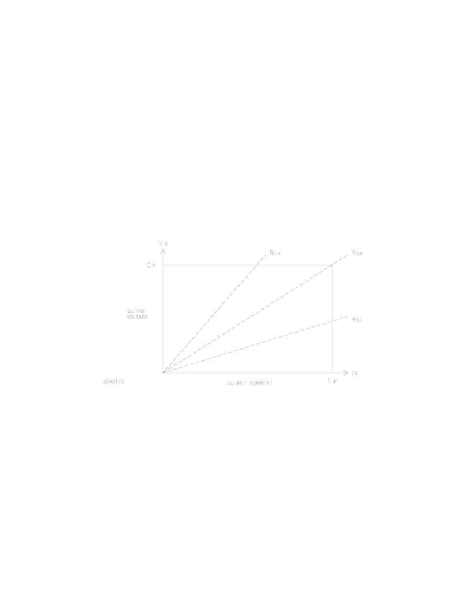
The output voltage E
o
and output current I
O
of the MBT Power Supply is determined by their pro-
grammed values and by the magnitude of the load resistance (R
L
). The crossover resistance
(R
LX
) is the load value at which, for given values of programmed voltage and current, the power
supply will switch from voltage mode (see PAR.s 4.1.1 and 4.1.3) to current mode (see PAR.s
4.1.2 and 4.1.4) or vice versa; R
LX
is given by Ohm's Law:
E
p
= I
p
R
LX
(see Figure 4-1)
FIGURE 4-1. CROSSOVER CHARACTERISTICS OF THE MBT POWER SUPPLY SHOWING THE
CRITICAL OR CROSSOVER VALUE OF LOAD RESISTANCE R
LX
4.1.1
VOLTAGE SOURCE.
When the Power Supply is programmed to operate as a voltage source with current limit, and
the load resistance becomes smaller than R
LX
(for example R
LI
in Figure 4-1), the MBT Power
Supply will go into current limit, generating an Overload error message. With a load resistance
larger than R
LX
(for example R
LV
in Figure 4-1), the MBT Power Supply will operate as a voltage
source and no error message will be issued. The actual output voltage E
O
is equal to the pro-
grammed voltage Ep, whereas the actual output current is determined by the load resistance R
L
according to Ohm's law:
E
O
=I
O
R
L