Table 2-4. internal jumper configuration, 9 rs 232 connections, Rs 232 connections -12 – KEPCO MBT Series User Manual
Page 36: Internal jumper configuration -12, 4 list
2-12
MBTSVC 111609
2.9
RS 232 CONNECTIONS
Since the MBT uses a 9-pin male connector, it is classified as a Data Terminal Equipment (DTE)
in accordance with the RS 232 Standard (equipment using a female connector is classified as
Data Communication Equipment, DCE).
Either a DTE to DTE or a null modem cable is required to connect the MBT-G to an IBM-PC
compatible computer. This cable has only three wires and connects RXD at one end to TXD at
the other end. The RS232-C port control lines (Table 2-2) are used to activate special feature by
means of jumpers, e.g., secondary addressing may be enabled by putting a jumper between
DSR and RTS at the RS 232 port (pins 6 and 7. Refer to PAR. 3.3.3.1 for RS 232 operation.
NOTE: Be sure the cable used has no unintended internal connections, particularly between
RTS and CTS.
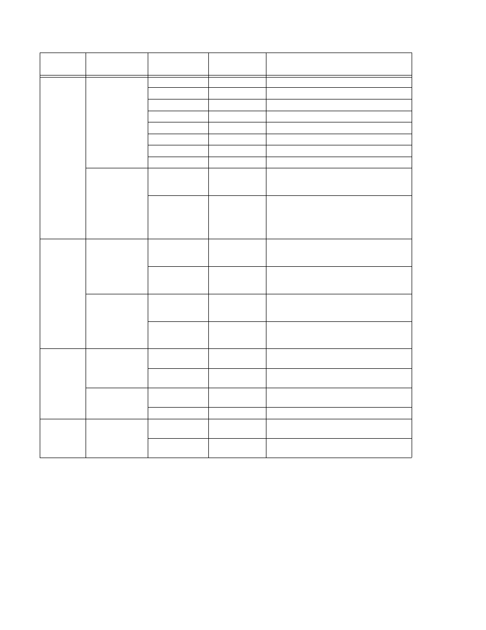
TABLE 2-4. INTERNAL JUMPER CONFIGURATION
LOCATION
FUNCTION
JUMPER
INSTALLED
JUMPER
NOT
INSTALLED
DESCRIPTION
A1
Establish the
Model
J1-J5
MBT 6-32M (G) (R)
J1-J4
J5
MBT 15-20M (G) (R)
J1-J3, J5
J4
MBT 25-14M (G) (R)
J1-J3
J4, J5
MBT 36-10M (G) (R)
J1, J2, J4, J5
J3
MBT 55-7M (G) (R)
J1, J2, J4
J3, J5
MBT 75-5M (G) (R)
J1, J2, J5
J3, J4
MBT 100-3.6M (G) (R)
J1, J2
J3-J5
MBT 150-2.4M (G) (R)
Path Fault
Protection
J7
(Default for
M, MG)
For M and MG units; enables crowbar protection
circuit to trip circuit breaker and shut off unit if
path fault detected.
J7
(Default for
MR, MGR)
For MR and MGR units; allows software com-
plete control of path fault protection. Outputs
(voltage and current) are programmed to zero
and relays opened to isolate load in case of path
fault.
A2
Input Power Loss
Protection
J5
(Default)
Enables crowbar protection circuit to trip circuit
breaker and shut off unit when power loss
detected.
J5
Disables crowbar protection circuit which trips
circuit breaker and shuts off unit when power
loss detected.
Control of OUT-
PUT ENABLED
Status Indicator
(M, MG Models
only)
J4 pins 1-2
(Default)
For M. MG units: front panel OUTPUT
ENABLED indicator illuminated only when the
output is enabled.
J4 pins 2-3
For M. MG units: front panel OUTPUT
ENABLED indicator illuminated whether or not
the output is enabled.
A13
Control of
Programming
Language
J7
(Default)
Selects SCPI programming language (see PAR.
3.3.5).
J7
Selects CIIL programming language (see PAR.
3.3.6).
Permits Selection
of Secondary
Address
J8
(Default)
Secondary address not allowed.
J8
Secondary address allowed.
A14
Determines
External Cable
Shield Connection
J5
(Default)
Connects shield of external IEEE 488 cable to
signal common.
J5
Disconnects shield of external IEEE 488 cable
from signal common.