Table 1-2. general specifications, General specifications -2, E 1-2 – KEPCO MBT Series User Manual
Page 18
1-2
MBTSVC111609
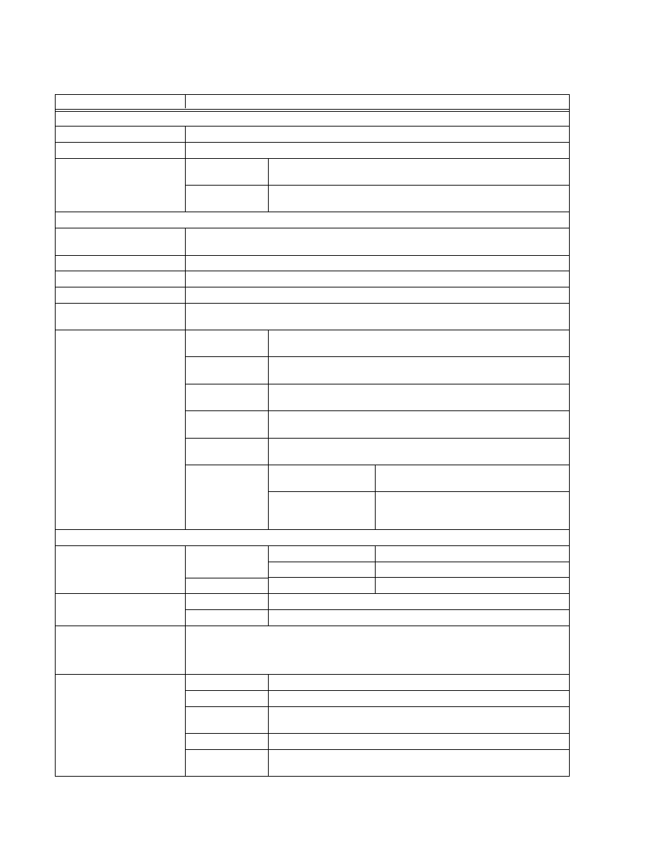
TABLE 1-2. GENERAL SPECIFICATIONS
CHARACTERISTIC
REQUIREMENT
INPUT
A-c Voltage (User selectable)
105-125V/210-250V a-c
A-c Input Frequency Range
47-63 Hz
A-c Input Current
115V a-c
(nominal)
7.5 Amperes
230V a-c
(nominal)
3.7 Amperes
OUTPUT
Voltage/Current Adjustment
Range
0 - 100% of rating, either continuously (inherent resolution), by step or by programmed setting.
Remote Sensing Range
0.5V per lead
D-C Isolation Voltage
500V d-c
Enable/Disable Output Power
Using front panel or via the Digital Bus.
Polarity Reversal
(MR and MGR models only)
Built-in polarity reversal power & sense relays.
Protection
Overvoltage
Tracks programmed voltage, crowbars output & turns off input circuit
breaker.
Overcurrent
Tracks programmed current, crowbars output & turns off input circuit
breaker.
Overtemperature
Monitors heatsink temperature, crowbars output & turns off input circuit
breaker.
External Polarity
Reversal
Built-in diode protects unipolar supply output.
Power Loss
Detects loss of a-c input power, disables output & turns
off input circuit breaker.
Overvoltage or
interruption
between Power
and Sensing Leads
MR and MGR Models:
Output voltage and current programmed to zero
and output relays opened.
M and MG Models:
Output voltage and current programmed to zero
and/or output crowbar activated and input circuit
breaker turned off
CONTROL-INDICATORS
Programming Resolution/Accu-
racy
Programming Resolution
Accuracy
Voltage
0.024% EOMAX (12 Bits) 0.024% EOMAX
Current
0.024% IOMAX (12 Bits) 0.1% IOMAX
Data Read-back Accuracy
Voltage
0.1% EOMAX
Current
0.15% IOMAX
Output Display
2X16 Char. Alphanumeric LCD with LED Backlight Indicates Output Voltage, Output Current, Sta-
tus and Menu. Output voltage displayed by four digits with either three, two, or one decimal(s),
depending on Model; output current displayed by either three or four digits (depending on Model)
with two decimals.
Indicators (LED)
VOLTAGE MODE
Green; lit when unit is in voltage mode.
CURRENT MODE
Amber; lit when unit is in current mode.
POLARITY
REVERSED
Red; lit when polarity reversed. (Operational for MR and MGR Models only.)
REMOTE
Green; lit when unit is operating in remote mode.
OUTPUT
ENABLED
Green; lit when output is enabled.