2 current source, 3 voltage mode, Figure 4-2. voltage comparison equivalent circuit – KEPCO MBT Series User Manual
Page 108: 4 current mode, Current source -2, Voltage mode -2, Current mode -2, Voltage comparison equivalent circuit -2, And 4.1.3) to c
4-2
MBTSVC111609
4.1.2
CURRENT SOURCE
Similarly, if the Power Supply is programmed to operate as a current source with voltage limit,
and the load resistance becomes larger than R
LX
(for example R
LV
in Figure 4-1) the MBT
Power Supply will go into voltage limit, generating an Overload error message. With a load
resistance smaller than R
L X
(for example R
L I
in Figure 4-1) the MBT Power Supply will operate
as a current source and no error message will be issued. The actual output current Io is equal to
the programmed current I
p
, whereas the actual output voltage is determined by the load resis-
tance R
L
according to the Ohm's Law:
E
o
= I
O
R
L
4.1.3
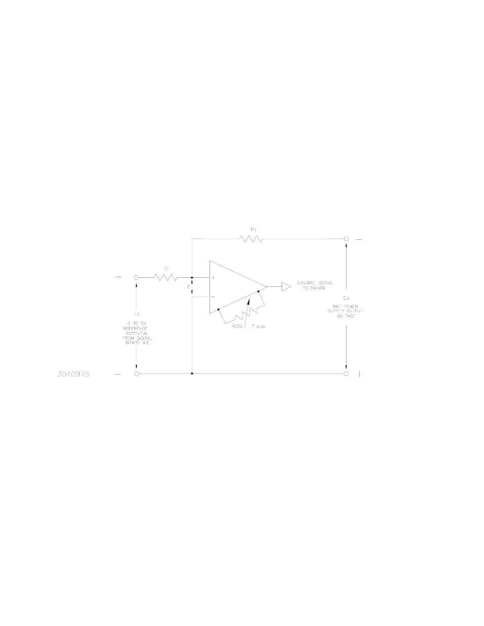
VOLTAGE MODE
In the voltage mode of operation, a voltage comparison amplifier compares the feedback signal
from the output voltage with a 0 to +5V Reference Potential generated from a Digital to Analog
Converter (DAC) from the Digital Board A3 (see Figure 4-2).
FIGURE 4-2. VOLTAGE COMPARISON EQUIVALENT CIRCUIT
A condition of balance exists if: E
o
/R
f
= E
i
/R
i
and
ε approaches zero. A change in either E
i
or
E
O
in the balance equation produces an error signal that, when amplified by the voltage compar-
ison amplifier, becomes a control signal for the MBT Power Supply driver stage. The control sig-
nal is then applied to the pass element (power transistors) to increase or decrease its
conductance so as to maintain a desired value of output voltage.
4.1.4
CURRENT MODE
In the current mode of operation, a current comparison amplifier compares a feedback signal
proportional to the output current, to a 0 to +5V Reference Potential. The Reference Potential is
generated by another channel of the Digital to Analog Converter on the Digital Board A3 (see
Figure 4-3).