1 troubleshooting – Epson 440 User Manual
Page 82
EPSON Stylus Color 440/640/740
Revision A
Chapter 3
Troubleshooting
82
3.1 Troubleshooting
The printer may exhibit different symptoms for the same problem, which
makes troubleshooting more difficult. This section, however, provides
simple and effective ways to facilitate troubleshooting.
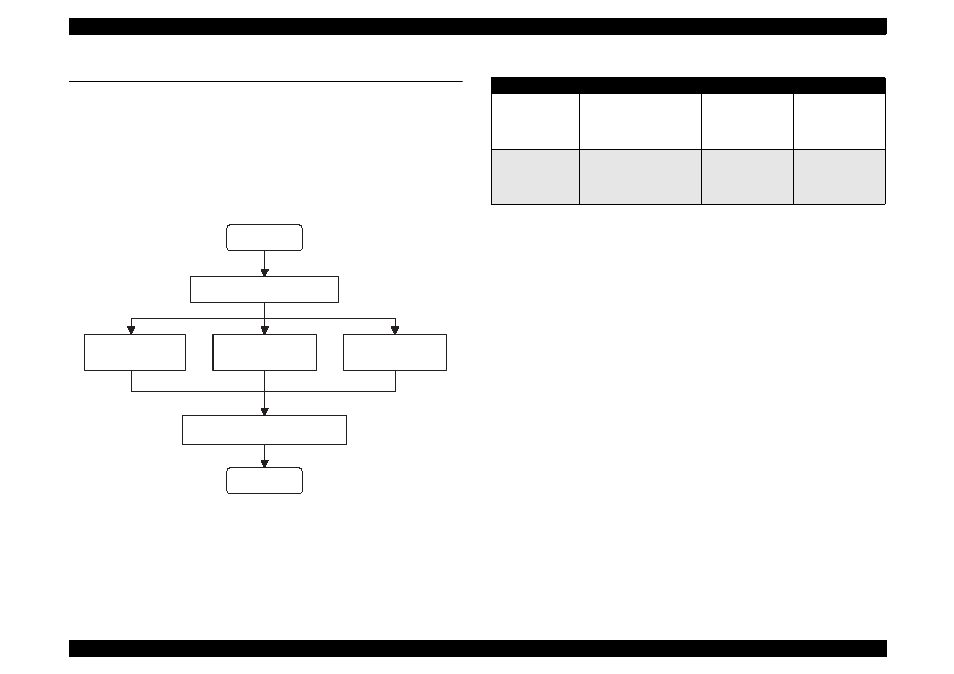
The following flowchart illustrates the main steps of the trouble shooting
process.
Figure 3-1. Troubleshooting Process Flowchart
Table 3-1. M otor Resistance and M easurem ent Procedure
* Main board refers to the following:
Stylus Color 440: C206Main-B, C255Main
Stylus Color 640: C256Main
Stylus Color 740: C257Main
See the following page for Table 3-2, “Sensor Check” and Table 3-3,
“Printer Condition and Panel Status”.
START
END
Unit Level Troubleshooting
Unit Repair
(PSB/PSE)
Unit Repair
(Main board)
Disassemble and Adjustment
Unit Repair
(Printer Mechanism)
Motor Name
Location
Check Point
Resistance
CR Motor
• Stylus Color 440/640
CN6 (Main board *)
• Stylus Color 740
CN7 (Main board *)
Pins 1 & 3,
Pins 2 & 4
7.8 Ohms
±
10%
PF (Pump) Motor
• Stylus Color 440/640
CN7 (Main board *)
• Stylus Color 740
CN8 (Main board *)
Pins 1 & 3,
Pins 2 & 4
7.8 Ohms
±
10%