3 serial interface (for stylus color 640, 740), 1 usb interface (only for stylus color 740) – Epson 440 User Manual
Page 31
EPSON Stylus Color 440/640/740
Revision A
Chapter 1
Product Description
31
1.3.3 Serial Interface (for Stylus Color 640, 740)
[Standard]
Based on RS-423
[Synchronization]
Synchronous
[Bit Rate]
Approx.1800Kbps
[Handshaking]
X-ON/X-OFF, DTR Protocol
[Word Format]
Data Bit= 8 bits
Parity Bit= None
Start Bit= 1 bit
Stop Bit= 1 bit
[Connector]
8-pin mini-circular connector
[Recommended Cable]Apple System Peripheral-8 Cable
Table 1-16. Pin Assignment
Table 1-17. X-On/X-Off and DTR Status
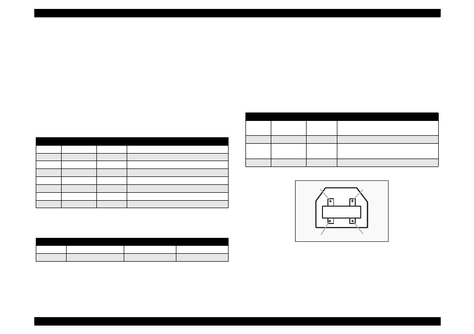
1.3.3.1 USB Interface (Only for Stylus Color 740)
[Standard]
Universal Serial Bus Specifications Rev. 1.0
Universal Serial Bus Device Class Definition
for Printing Device Version 1.0
[Bit Rate]
12 M bps
[Data Encoding]
NRZI
[Connector]
USB Series B
[Recommended Cable Length]
2 meters
Table 1-18. Pin Assignment
Figure 1-10. USB Pin Assignment
Pin No.
Signal Name
I/O
Description
1
SCLK
O
Synchronous clock signal
2
CTS
I
Clear To Send
3
TXD-
O
Transmit Data (-)
4
SG
I
(Signal Ground)
5
RXD-
I
Receive Data (-)
6
TXD+
O
Balanced Transmit Data (+)
7
DTR
O
Data Terminal Ready
8
RXD+
I
Balanced Receive Data (+)
State
Buffer Space
X-ON/X-OFF
DTR
Busy
Less than 3072 bytes
Send X-OFF code
OFF
Ready
More than 5120 bytes
Send X-ON code
ON
Pin No.
Signal Name
I/O
Description
1
Vcc
----
Cable power, Maxi. power consumption
is 100 mA
2
-Data
Bi-D
Data
3
+Data
Bi-D
Data, pull up to +3.3 V via 1.5 K ohms
resistor
4
Ground
----
Cable Ground
Pin #1
Pin #2
Pin #3
Pin #4