Epson 440 User Manual
Page 167
EPSON Stylus Color 440/640/740
Revision A
Chapter 7
Appendix
167
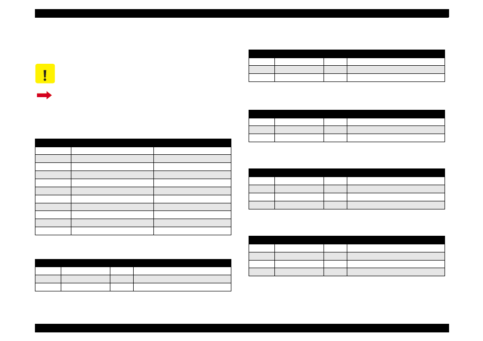
A.1.2.1 Connector Pin Assignment
(Stylus Color 740)
Tables in this section provide connector pin assignments of the
C257MAIN, the main board equipped with Stylus Color 740.
C A U T I O N
Information contained in this section only applies to
Stylus Color 740.
If you need information on Stylus Color 440 and Stylus
Color 640, return to Section A.1.1.1.
Table A-11. Connector Summary of C257MAIN
Connector
Function
Table to refer to
CN1
Parallel I/F connector
Chapter 1/Table 1-10
CN2
Serial I/F connector
Chapter 1/Table 1-16
CN3
SUB I/F connector
Chapter 1/Table 1-18
CN4
To HP sensor
CN5
To PE sensor
CN6
To ASF sensor
CN7
To CR motor
CN8
To PF motor
CN9
To Printhead
CN10
To Power supply board
CN11
To Control panel
Table A-12. Connector CN4
Pin
Signal Name
I/O
Function
1
HP
In
Sensor detect signal
2
GND
---
Ground
3
HPV
---
Sensor power supply(+5V)
Table A-13. Connector CN5
Pin
Signal Name
I/O
Function
1
PE
In
Sensor detect signal
2
GND
---
Ground
3
PEV
---
Sensor power supply (+5V)
Table A-14. Connector CN6
Pin
Signal Name
I/O
Function
1
ASF
In
Sensor detect signal
2
GND
---
Ground
3
ASFV
---
Sensor power supply (+5V)
Table A-15. Connector CN7
Pin
Signal Name
I/O
Function
1
CRA
Out
Phase drive signal (A)
2
CR-A
Out
Phase drive signal (-A)
3
CRB
Out
Phase drive signal (B)
4
CR-B
Out
Phase drive signal (-B)
Table A-16. Connector CN8
Pin
Signal Name
I/O
Function
1
PFA
Out
Phase drive signal (A)
2
PFB
Out
Phase drive signal (B)
3
PF-A
Out
Phase drive signal (-A)
4
PF-B
Out
Phase drive signal (-B)