Epson 440 User Manual
Page 75
EPSON Stylus Color 440/640/740
Revision A
Chapter 2
Operating Principles
75
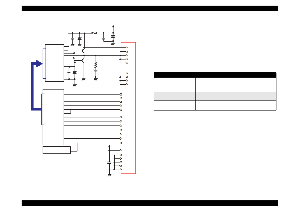
Figure 2-34. Head Drive Circuit for Stylus Color 740
[Common drive circuit]
The shape of trapezoidal wave form will be different according to the
printing operation, slight vibrations at the non-printing nozzle and
waiting condition. However, the IC6(for Stylus Color 440), IC7(for Stylus
Color 640), IC14(for Stylus Color 740) generates all wave forms as
drive wave forms by resistance(electric) welding control of common
voltage drive control signal that is output from the IC2(gate array) in the
figure above.
Table 2-9.
Specifications of H8D2813/CXA20995 for Stylus Color 440, 640, 740
This common voltage trapezoidal wave form can be observed anytime
after the +5V rises even if there is printing data or not. (Q7:3-pin,Q9:3-
pin for Stylus Color 440 and Q2: 3-pin, Q3: 3-pin for Stylus Color 640,
740)
[Nozzle Selector Drive Circuit]
In order to motivate the print head to carry out printing, it is necessary to
transmit the printing data to the appropriate nozzles, which becomes
direct signals to drive PZT. This data transmission is performed by the
serial method, however the data output for each black and CMY head is
transmitted by the parallel method.
CXA20996(IC14)
VCC45
Vcc45_2
NPNB
FB
PNPB
VOUTGND
F1
E05B588(IC2)
VHCTL
22
20
CCO
LAT
CLK
BCO
THM
1
2
5
14
11
3
190
SWC0
184
HLAT
IECLK
AN0
105
A0
A1
A2
A3
CLK1
CLK2
/FLOOR
/RST
DATA
DCLK
/E
HWA0
HWA1
HWA2
HWA3
HWCLK1
HWCLK2
/HWFLR
/HWRST
HWSDATA
HWSCLK
/HWSLAT
SI1
12
174
HNCHG
+42
23
18
16
22
21
20
19
26
25
24
23
GND2
GND2
GND2
GND2
COM
COM
COM
COM
VHV
27
VCC5
+5
24
14
SWC1
189
173
NCHG
16
HCLK
175
176
HSI1
SI2
HSI2
177
10
SI3
HSI3
178
8
SI4
9
179
HSI4
SI5
HSI5
180
7
SI6
HSI6
181
TMP95C061(IC1)
GND
GND
GND
GND
GND
+5
GND
18
17
15
13
6
4
CN9
Items
COntents
Drive Power Voltage
42
±
5%
Starts supplying after 5V rises and be stabilized./
Stops supplying before +5V drops.
Final Drive Element
2SC3746(for charging),
2SA1469(for discharging)
Operation at the Reset
Off on the both charging and discharging sides.
Supplies drive power source.