Epson 440 User Manual
Page 69
EPSON Stylus Color 440/640/740
Revision A
Chapter 2
Operating Principles
69
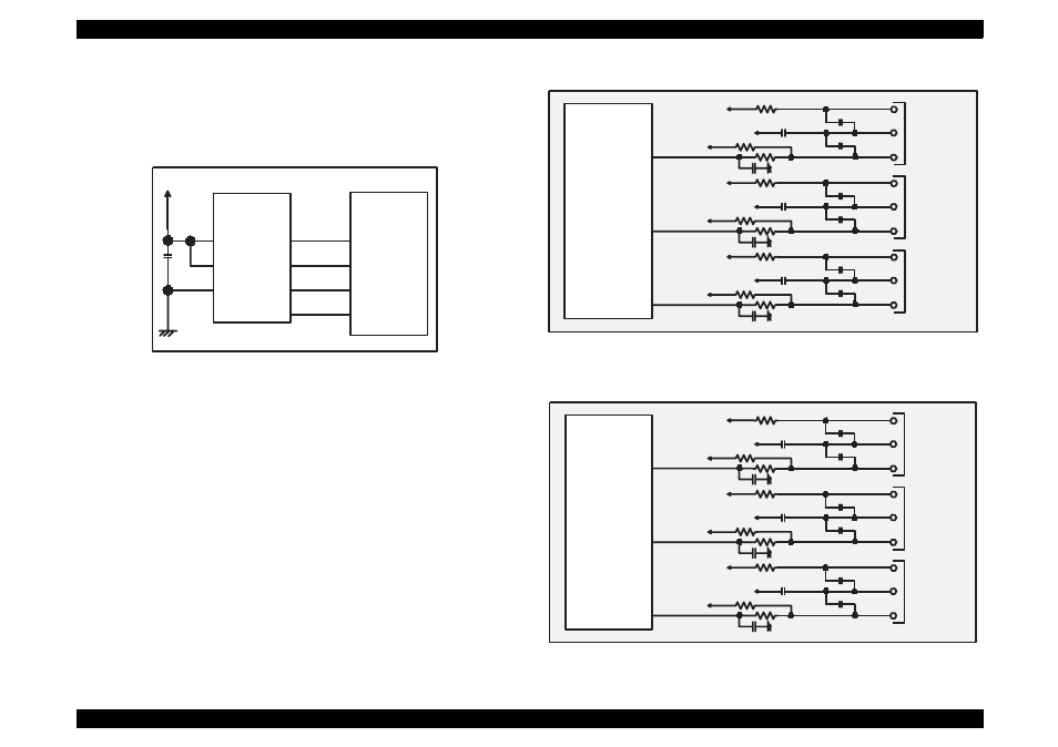
The following three figures show the sensor circuits. Out of the data
such as EPW with IEEE 1284 Nibble mode to be returned to the host,
the data to indicate ink consumption is calculated and managed by the
counter of the firmware. Therefore, it is omitted here.
Figure 2-23. Figure 5-23. Sensor Circuit for Stylus Color 440
Figure 2-24. Figure 5-24. Sensor Circuit for Stylus Color 640
Figure 2-25. Sensor Circuit for Stylus Color 740
+5V
8
6
5
AT93C46
(IC11)
Vcc
GND
ORG
E05B44
(IC2)
127
128
126
125
1
2
3
4
CS
SK
DI
DO
ECS
ECK
ECO
ECI
IC 2
E05B43
+5V
+5V
CN11
CN5
CN4
ASF
HP
PE
PE
GND
PEV
HP
GND
HPV
ASF
GND
ASFV
+5V
+5V
+5V
+5V
+5V
+5V
+5V
206
SW4
204
SW5
202
SW6
IC 2
E05B588
+5V
+5V
CN4
CN5
CN6
ASF
HP
PE
PE
GND
PEV
HP
GND
HPV
ASF
GND
ASFV
+5V
+5V
+5V
+5V
+5V
+5V
+5V
97
SWA0
98
SWA1
99
SWA2
- C8230 (29 pages)
- 400 (38 pages)
- 400 (148 pages)
- 600 (135 pages)
- 640 (45 pages)
- 700 (10 pages)
- 850 (147 pages)
- 1520 (40 pages)
- C82314 (71 pages)
- RS-485 (2 pages)
- 6200A (97 pages)
- C82307 (37 pages)
- UB E02 (86 pages)
- 440 (240 pages)
- 660 (92 pages)
- 5000 (154 pages)
- 5000 (176 pages)
- 9000 (68 pages)
- ARM.POWERED ARM720T (224 pages)
- SD-DSPUSBB (2 pages)
- CMD-2260 (18 pages)
- C823301 (17 pages)
- S1C6200A (98 pages)
- 33+ (10 pages)
- FEH300b (46 pages)
- SED 1520 Series (40 pages)
- Serial Interface GQ-3500 (13 pages)
- ETX-945 (39 pages)
- Photo EX (35 pages)
- C82364 (279 pages)
- 214D-1 (57 pages)
- EM07ZS1647F (168 pages)
- Connect-It SD-DSWIFIB (2 pages)
- ACTIONPC 7000 (10 pages)
- S5U1C63000H2 (35 pages)
- C824 (4 pages)
- C82069* (46 pages)
- 80211b (68 pages)
- C82312 (13 pages)
- S5U1C17801T1100 (60 pages)
- C82324* (57 pages)
- C82372 (22 pages)
- C82315 (48 pages)
- P07303 (36 pages)