Epson 440 User Manual
Page 156
EPSON Stylus Color 440/640/740
Revision A
Chapter 6
Maintenance
156
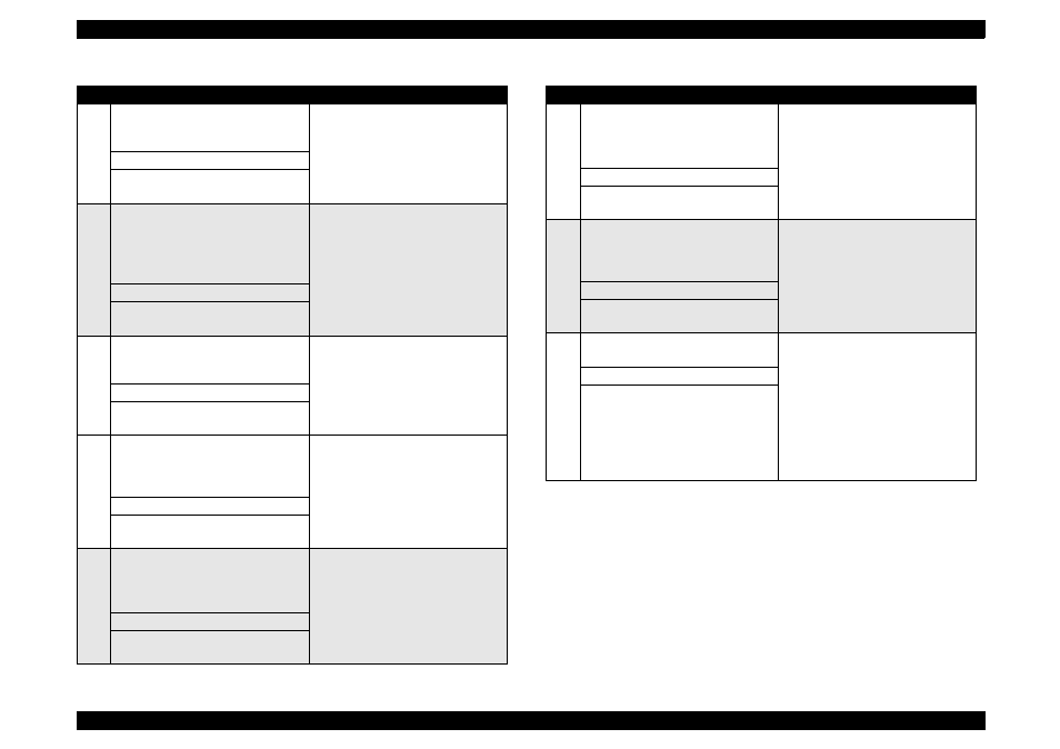
5
The shaft for “GEAR, 16, 40.8” on
“FRAME, LEFT”
Use a syringe to apply it.
Approximately 5-mm long
6
Bushings for “ROLLER, PF”
Left: Inside the bushing
Right: Inside the bushing (near the
pump assembly)
For the right bushing, apply it from
the paper path side, and wipe off any
grease sticking out to the cap
assembly side.
Rotate “ROLLER, PF” after applying
grease to evenly distribute it in the
bushing.
Use a syringe to apply it.
Approximately 3 mm diametrically
7
Both Left/Right Bushings for
“ROLLER, EXIT”
Avoid applying grease around the
paper path.
Use a syringe to apply it.
Evenly apply inside the bushings.
8
Contact points between “HOLDER,
PULLEY, DRIVEN” and “FRAME,
UPPER”
Verify that the holder slides only with
spring force after applying grease.
Use a syringe to apply it.
2-mm long for each point
9
ASF;
The round hole in the right frame of
ASF (to hold the roller shaft)
Avoid applying grease to “ROLLER,
ASSEMBLY, LD”.
Evenly apply inside the hole.
Table 6-2. Lubrication Point
No.
Standard
Remarks
10
ASF;
Contact points between “HOPPER”
and “LEVER, HOPPER, RELEASE”
Completely wipe off any grease
sticking out to the inner side of ASF.
Evenly apply lubrication to the points.
11
The round cutout in the left frame of
ASF (“GEAR, 34” is inserted to the
cutout.)
Completely wipe off any grease
sticking out to the inner side of ASF.
Evenly apply inside the hole
12
Oil pad in the carriage assembly
Lubricate the oil pad only when;
*Replacing the carriage assembly
*Replacing the oil pad
Use a precise syringe to apply it. If
you accidentally apply too much oil to
the oil pad, throw the pad away and
take a new one again.
Leave the oil pad for a while to wait
until oil is evenly infiltrated, then
install it on the carriage assembly.
0.7 cc
Note:
This is the amount to be applid to a
new oil pad.
Table 6-2. Lubrication Point
No.
Standard
Remarks