Epson 440 User Manual
Page 149
EPSON Stylus Color 440/640/740
Revision A
Chapter 5
Adjustment
149
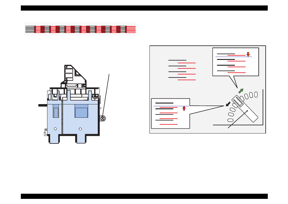
Figure 5-28. Sample of Head Angular Adjustment Pattern
5. Loosen the printhead securing screw securing the printhead on the
carriage. (You don
'
t need to remove it completely.)
Figure 5-29. . Screw Position
NOTE: Make sure to loosen this screw. Otherwise, the printhead
angle will no change even if the adjusting lever moves.
6. Look at the black/magenta combination in the pattern and move the
adjusting lever to make the magenta lines stay between the black
lines with even space. The figure below shows how the pattern
changes as the adjusting lever moves right (rear) or left (front).
Figure 5-30.
Lever Operation and Corresponding Change in Pattern
Head Angular Adjustment Pattern (BK-M)
Printhead securing screw
To move this up,
Correct condition = evenly spaced
move the lever to
the left (front).
move the lever to the
right (rear).
Adjusting Lever
To move this down,
- C8230 (29 pages)
- 400 (38 pages)
- 400 (148 pages)
- 600 (135 pages)
- 640 (45 pages)
- 700 (10 pages)
- 850 (147 pages)
- 1520 (40 pages)
- C82314 (71 pages)
- RS-485 (2 pages)
- 6200A (97 pages)
- C82307 (37 pages)
- UB E02 (86 pages)
- 440 (240 pages)
- 660 (92 pages)
- 5000 (154 pages)
- 5000 (176 pages)
- 9000 (68 pages)
- ARM.POWERED ARM720T (224 pages)
- SD-DSPUSBB (2 pages)
- CMD-2260 (18 pages)
- C823301 (17 pages)
- S1C6200A (98 pages)
- 33+ (10 pages)
- FEH300b (46 pages)
- SED 1520 Series (40 pages)
- Serial Interface GQ-3500 (13 pages)
- ETX-945 (39 pages)
- Photo EX (35 pages)
- C82364 (279 pages)
- 214D-1 (57 pages)
- EM07ZS1647F (168 pages)
- Connect-It SD-DSWIFIB (2 pages)
- ACTIONPC 7000 (10 pages)
- S5U1C63000H2 (35 pages)
- C824 (4 pages)
- C82069* (46 pages)
- 80211b (68 pages)
- C82312 (13 pages)
- S5U1C17801T1100 (60 pages)
- C82324* (57 pages)
- C82372 (22 pages)
- C82315 (48 pages)
- P07303 (36 pages)