4 timer circuit – Epson 440 User Manual
Page 71
EPSON Stylus Color 440/640/740
Revision A
Chapter 2
Operating Principles
71
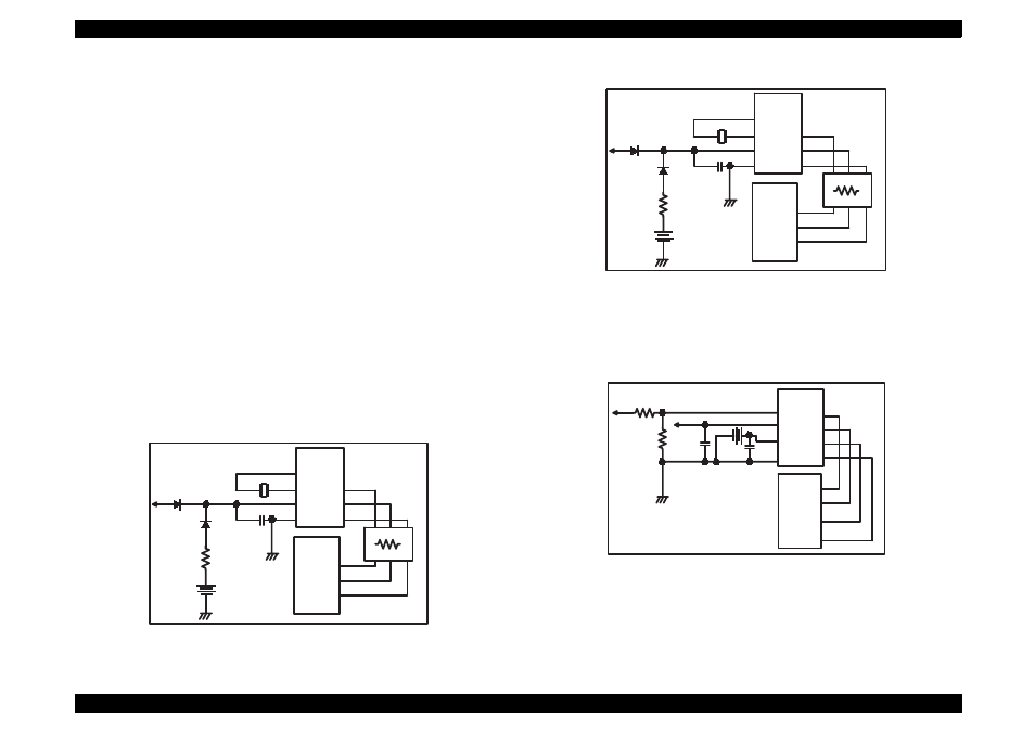
2.2.4.4 Timer Circuit
A lithium battery is mounted on the main board and calculates how long
the printer is not used. The timer IC starts counting with oscillation
motivated by the crystal oscillator using this battery as a power source.
The following figures show connection of the Timer circuit. The
followings explain about operation of this circuit.
When the printer is on, power is supplied to the Timer IC by
applying +5V quickly through the D1.
This power is also used for the power to oscillator. The
oscillation wave form is input to XI terminal.
Since the oscillation wave form of CR1 is analog wave form, it is
processed into the pulse form in the Timer IC.
When the printer is turned on, the Timer IC outputs power off
time as serial data to the gate array.
Once the printer is turned off, 3VDC of BAT1(lithium battery) is
supplied as power source for the Timer IC through D7.
Since +5V at the power on is higher than +3V of the lithium
battery, the power is not being consumed from the lithium
battery.
Figure 2-29. Timer Control Circuit for Stylus Color 440
Figure 2-30. Timer Counter Circuit for Stylus Color 640
Figure 2-31. Timer Counter Circuit for Stylus Color 740
+5
Batt1
D7
D1
C4
0.1u
S-3510ANF
(IC5)
X I
X O
2
3
VCC
GND
8
4
5
6
7
123
121
124
CR1
E05B44
(IC2)
TCE
TCLK
TDATA
RM7
CS
/SCK
/SIO
+5
Batt1
D1
D4
C4
0.1u
S-3510ANF
(IC10)
XI
XO
2
3
VCC
GND
8
4
5
6
7
125
123
126
CR3
E05B43
(IC2)
TCE
TCLK
TDATA
RM7
CS
/SCK
/SIO
+42
RTC-9810
(IC8)
Vin
9
7
8
5
6
4
CE
SCLK
Data
Vdd
Vbk
GND
20
21
23
E05B588
(IC2)
TMCS
TMCK
TMDATA
/RST
2
25
+5
14
Batt1