2 removing the right and left ld roller assembly – Epson 440 User Manual
Page 122
EPSON Stylus Color 440/640/740
Revision A
Chapter 4
Disassembly and Assembly
122
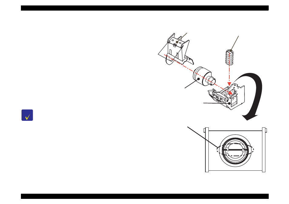
4.2.4.6.2 Removing the Right and Left LD Roller Assembly
1. Disassemble the ASF assembly and remove the paper feed roller
assembly and hopper assembly from the ASF assembly. (Refer to
Section 4.2.4.6.)
2. Take out the right and left compression springs 1.66 from the back
of the hopper assembly.
3. Pull out the cam part of the hopper assembly from the hole located
on the frame of the right LD roller assembly,
4. Pull out the LD roller shaft. The paper feed roller assembly and
hopper assembly should be disconnected by now.
5. Release the hook of LD roller assembly at the shaft hole of the
paper feed roller assembly. Also, release the fixed hook of the cover
roller LD and remove the LD roller assembly.
Figure 4-17. Disassembly of Paper Feed Roller Assembly
C H E C K
P O I N T
When installing the LD roller assembly, make sure
that the hooks are hung on the paper feed assembly.
During assembly, when setting the compression
spring 1.66 to the spring installation position in the
paper feed assembly, hang the spring on the hook
temporarily. Also, do not forget to release the hooks
of these springs from the holes located on the back of
paper feed assembly by rotating the spring. (Refer to
the figure below.)
C o m p r e s s i o n S p r i n g 1 . 6 6
L D R o l l e r A s s e m b l y
( R i g h t a n d L e f t )
P a p e r F e e d A s s e m b l y
( R i g h t a n d L e f t )
L D R o l l e r C o v e r
( R i g h t a n d L e f t )
+
P a p e r F e e d H o l d e r S h e e t
D u r i n g a s s e m b l y , s e t t h e c o m p r e s s i o n s p r i n g 1 . 6 6 i n
t h e p o s i t i o n f o r s p r i n g i n s t a l l a t i o n o f t h e p a p e r f e e d
a s s e m b l y a n d h a n g t h e b e n t p a r t o f t h e s p r i n g o n t h e h o o k .