A.1.1 connector summary (stylus color 440/640) – Epson 440 User Manual
Page 162
EPSON Stylus Color 440/640/740
Revision A
Chapter 7
Appendix
162
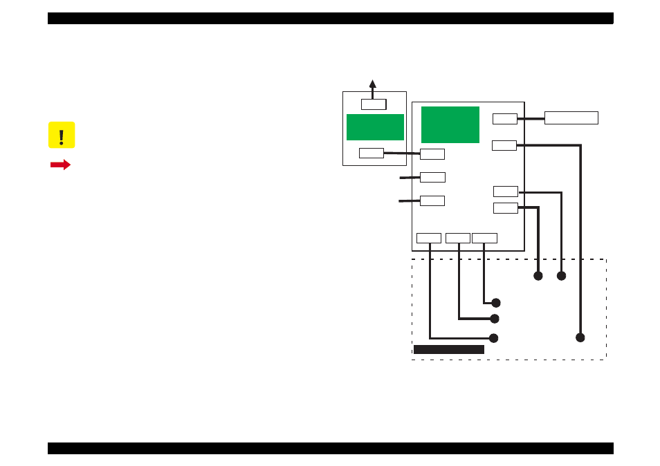
A.1.1 Connector Summary
(Stylus Color 440/640)
This section provides information on connectors in the main units of the
Stylus Color 440 and Stylus Color 640. Figure 1 shows how the main
component units are connected.
Figure A-1. Cable Connection of Stylus Color 440/640
C A U T I O N
Information contained in this section only applies to
Stylus Color 440 and Stylus Color 640.
If you need information on Stylus Color 740, go to
Section A.1.2.
CN1
CN2
AC
CN10
CN3
CN8
C206MAIN-B
C255MAIN
C256MAIN
(Main Board)
CN1
CN2
CN6
CN7
CN11
CN5
CN4
Control Panel
Print Head
CR
Motor
PF
Motor
ASF Sensor
HP Sensor
PE Sensor
Parallel I/F
Printer Mechanism
C206PSB/PSE
(Power Supply
Board)
Serial I/F
(Not mounted)
See also other documents in the category Epson Hardware:
- C8230 (29 pages)
- 400 (38 pages)
- 400 (148 pages)
- 600 (135 pages)
- 640 (45 pages)
- 700 (10 pages)
- 850 (147 pages)
- 1520 (40 pages)
- C82314 (71 pages)
- RS-485 (2 pages)
- 6200A (97 pages)
- C82307 (37 pages)
- UB E02 (86 pages)
- 440 (240 pages)
- 660 (92 pages)
- 5000 (154 pages)
- 5000 (176 pages)
- 9000 (68 pages)
- ARM.POWERED ARM720T (224 pages)
- SD-DSPUSBB (2 pages)
- CMD-2260 (18 pages)
- C823301 (17 pages)
- S1C6200A (98 pages)
- 33+ (10 pages)
- FEH300b (46 pages)
- SED 1520 Series (40 pages)
- Serial Interface GQ-3500 (13 pages)
- ETX-945 (39 pages)
- Photo EX (35 pages)
- C82364 (279 pages)
- 214D-1 (57 pages)
- EM07ZS1647F (168 pages)
- Connect-It SD-DSWIFIB (2 pages)
- ACTIONPC 7000 (10 pages)
- S5U1C63000H2 (35 pages)
- C824 (4 pages)
- C82069* (46 pages)
- 80211b (68 pages)
- C82312 (13 pages)
- S5U1C17801T1100 (60 pages)
- C82324* (57 pages)
- C82372 (22 pages)
- C82315 (48 pages)
- P07303 (36 pages)