3 eeprom control circuits – Epson 440 User Manual
Page 70
EPSON Stylus Color 440/640/740
Revision A
Chapter 2
Operating Principles
70
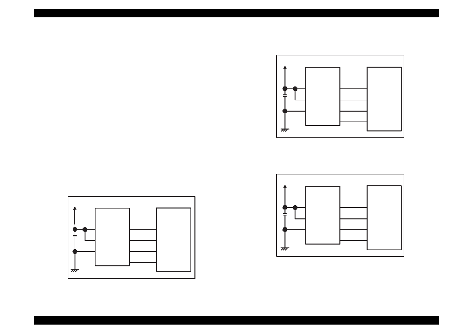
2.2.4.3 EEPROM Control Circuits
The EEPROM of Stylus Color 440/640/740 has following contents. Gate
array controls operations of reading data when the power is on and
writing data when the power is off.
Ink consumption (Bk, CMY)
CL counter (Various cleaning operations that are previously
done are memorized)
Destination information
Information of various adjustment values (Bi-D, VH voltage, etc.)
CPSI pass word
Other various setting values by the user
EEPROM is connected to the Gate array by 4 lines and performs
following functions. The figure below shows EEPROM control circuit.
CS:
Chip selection signal
CK:
Data synchronism clock pulse
DI:
Data writing line (serial data) at power off.
DO:
Data reading line (serial data) at power on.
Figure 2-26. EEPROM Control Circuit for Stylus Color 440
Figure 2-27. EEPROM Control Circuit Stylus Color 640
Figure 2-28. EEPROM Control Circuit for Stylus Color 740
+5V
8
6
5
AT93C46
(IC11)
Vcc
GND
ORG
E05B44
(IC2)
127
128
126
125
1
2
3
4
CS
SK
DI
DO
ECS
ECK
ECO
ECI
+5V
8
6
5
AT93C46
(IC11)
Vcc
GND
ORG
E05B43
(IC2)
130
129
128
127
1
2
3
4
CS
SK
DI
DO
ECS
ECK
ECO
ECI
+5V
8
6
5
AT93C46
(IC7)
Vcc
GND
ORG
E05B588
(IC2)
206
205
204
203
1
2
3
4
CS
SK
DI
DO
EECS
EECK
EECO
EECI