Clips. see figure 4-1, Warning – Emerson Process Management MICRO MOTION 2400S User Manual
Page 27
Configuration and Use Manual
19
Connecting with ProLink II or Pocket ProLink Software
St
a
rt
u
p
Usin
g P
ro
L
in
k II
T
ransmitter User
Interface
Be
fo
re
Y
o
u
Begin
St
a
rt
u
p
Usin
g P
ro
L
in
k II
T
ransmitter User
Interface
Be
fo
re
Y
o
u
Begin
St
a
rt
u
p
Usin
g P
ro
L
in
k II
T
ransmitter User
Interface
Be
fo
re
Y
o
u
Begin
St
a
rt
u
p
Usin
g P
ro
L
in
k II
T
ransmitter User
Interface
Be
fo
re
Y
o
u
Begin
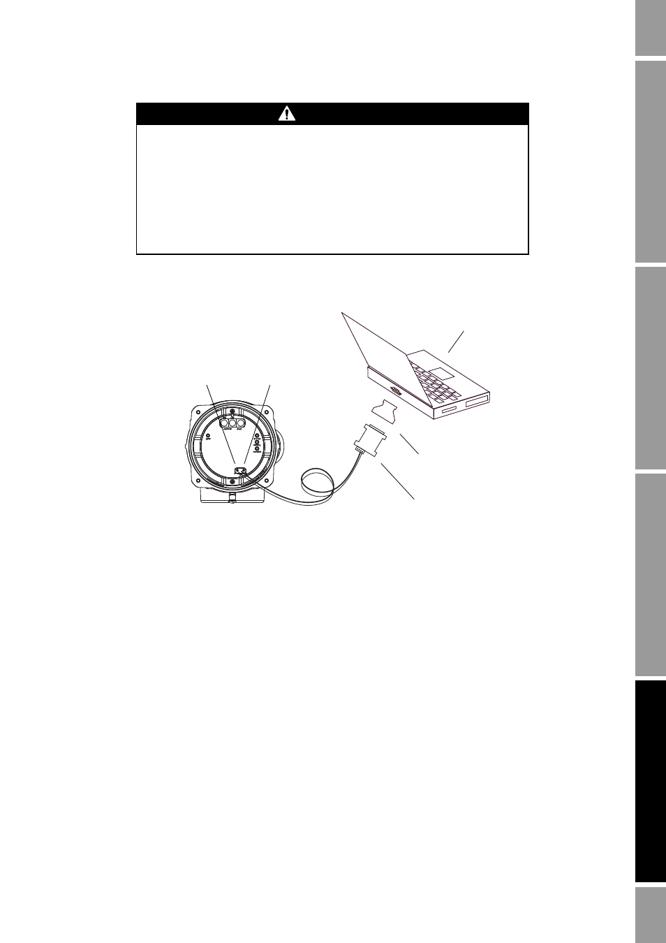
Figure 4-1
Serial port connections to service port clips
3. Start ProLink II or Pocket ProLink. In the Connection menu, click
Connect to Device
. In the
screen that appears, specify:
•
Protocol
:
Service Port
•
COM Port
: as appropriate
No other parameters are required.
4. Click
Connect
. The software will attempt to make the connection.
5. If an error message appears:
a.
Swap the leads between the two service port clips and try again.
b.
Ensure that you are using the correct COM port.
c.
Check all the wiring between the PC and the transmitter.
d. Verify the RS-485 to RS-232 signal converter.
WARNING
Removing the transmitter housing cover in a hazardous area can cause an
explosion.
Because the transmitter housing cover must be removed to connect to the service
port clips, the service port clips should be used only for temporary connections,
e.g., for configuration or troubleshooting purposes.
When the transmitter is in an explosive atmosphere, use a different method to
connect to your transmitter.
Service port clips
RS-485 to RS-232
signal converter
25-pin to 9-pin serial port
adapter (if necessary)
RS-485/A
RS-485/B
PC