See figure 10-8 – Emerson Process Management MICRO MOTION 2400S User Manual
Page 113
Configuration and Use Manual
105
Measurement Performance
Me
asu
reme
nt P
er
form
anc
e
Defaults
T
rou
b
lesho
o
ti
ng
Compensation
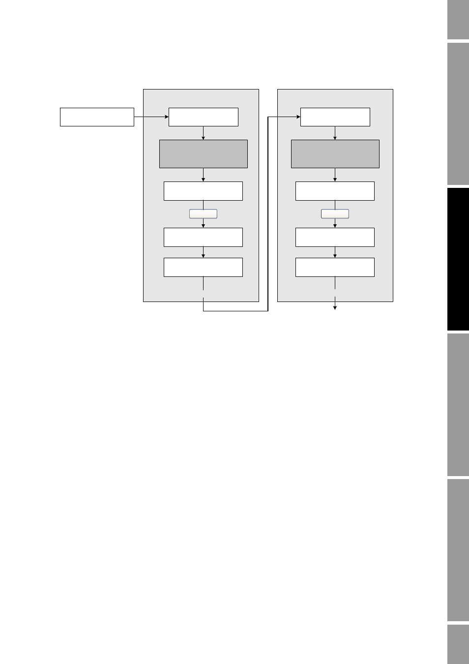
Figure 10-8
D1 and D2 density calibration – ProLink II
Enter density of D1 fluid
Calibration in Progress
light turns green
Calibration in Progress
light turns red
D1 calibration
Close shutoff valve
downstream from sensor
Fill sensor with D1 fluid
Fill sensor with D2 fluid
Close
Enter density of D2 fluid
Calibration in Progress
light turns green
Calibration in Progress
light turns red
D2 calibration
Close
Done
Do Cal
Do Cal
ProLink Menu >
Calibration >
Density cal – Point 1
ProLink Menu >
Calibration >
Density cal – Point 2