10 (2) brake signal (/bk) setting – Yaskawa Sigma-5 User Manual: Design and Maintenance - Linear Motors MECHATROLINK-III Communications Reference User Manual
Page 98
4 Operation
4.3.4 Holding Brakes
4-10
(2) Brake Signal (/BK) Setting
This output signal controls the brake. The allocation of the /BK signal can be changed. Refer to (3) Brake Sig-
nal (/BK) Allocation for allocation.
The /BK signal turns OFF (applies the brake) when an alarm is detected or the SV_OFF command is received.
The brake OFF timing can be adjusted with Pn506.
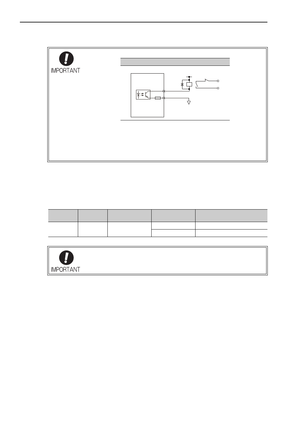
• Configure the relay circuit to apply the holding brake by the emergency stop.
• The allocation of the /BK signal can be changed. Refer to (3) Brake Signal (/BK) Allo-
cation to set the parameter Pn50F.
• When using a 24-V brake, separate the 24-VDC power supply from other power sup-
plies, such as the one used for the I/O signals of CN1 connectors. Always install the
24-VDC power supply separately. If the power supply is shared, the I/O signals might
malfunction.
Relay Circuit Example
0 V
Emergency stop
5 to 24 VDC
SERVOPACK
Photocoupler
Type
Name
Connector
Pin Number
Setting
Meaning
Output
/BK
CN1-1, CN1-2
ON (closed)
Releases the brake.
OFF (open)
Applies the brake.
The /BK signal is still ON during overtravel and the brake is still released.