2 list of monitor displays – Yaskawa Sigma-5 User Manual: Design and Maintenance - Linear Motors MECHATROLINK-III Communications Reference User Manual
Page 343
9.2 List of Monitor Displays
9-45
9
Ap
pend
ix
9.2 List of Monitor Displays
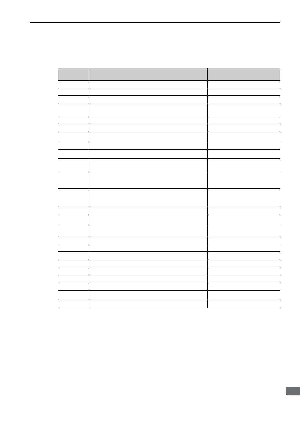
The following list shows the available monitor displays.
∗1. For details, refer to 7.3 Monitoring Input Signals.
∗2. For details, refer to 7.4 Monitoring Output Signals.
∗3. For details, refer to 4.4.3 Electronic Gear.
Parameter
No.
Description
Unit
Un000
Motor moving speed
mm/s
Un001
Speed reference
mm/s
Un002
Internal force reference (in percentage to the rated force)
%
Un003
Electric angle 1 (number of linear-scale pulses from polarity
origin: decimal display)
linear scale pulse
*3
Un004
Electric angle 2 (from polarity origin (electric angle))
deg
Un005
*1
Input signal monitor
−
Un006
*2
Output signal monitor
−
Un007
Input reference pulse speed (valid only in position control)
mm/s
Un008
Position error amount (valid only in position control)
reference unit
Un009
Accumulated load ratio (in percentage to the rated force: effec-
tive force in cycle of 10 seconds)
%
Un00A
Regenerative load ratio (as a percentage of the processable
regenerative power: regenerative power consumption in cycle
of 10 seconds)
%
Un00B
Power consumed by DB resistance
(in percentage to the processable power at DB activation: dis-
played in cycle of 10 seconds)
%
Un00C
Input reference pulse counter
reference unit
Un00D
Feedback pulse counter
linear scale pulse
*3
Un010
Allowable motor maximum speed and encoder output resolu-
tion
−
Un011
Hall sensor signal
−
Un012
Total operation time
100 ms
Un013
Feedback pulse counter
reference unit
Un014
Effective gain monitor (gain settings 1 = 1, gain settings 2 = 2)
−
Un015
Safety I/O signal monitor
−
Un020
Motor rated speed
mm/s
Un021
Motor maximum speed
mm/s
Un084
Linear scale pitch (Scale pitch = Un084
× 10
Un085
[pm])
−
Un085
Linear scale pitch index (Scale pitch = Un084
× 10
Un085
[pm])
−