Yaskawa Sigma-5 User Manual: Design and Maintenance - Linear Motors MECHATROLINK-III Communications Reference User Manual
Page 327
9.1 List of Parameters
9-29
9
Ap
pend
ix
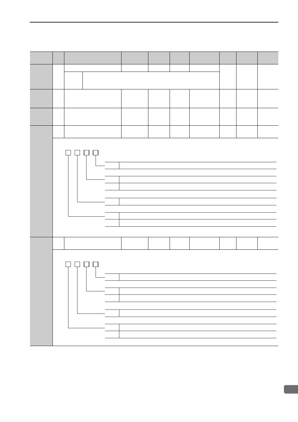
Pn825
2
Option Monitor 2 Selection
–
–
0000
Immediately
Setup
−
*1
0000H
to
0084H
Same as Option Monitor 1 Selection.
Pn827
2
Linear Deceleration Constant
1 for Stopping
1 to 65535
10000
reference
unit/s
2
100
Immediately
*5
Setup
−
*1
Pn829
2
SVOFF Waiting Time
(SVOFF at deceleration to
stop)
0 to 65535
10 ms
0
Immediately
*5
Setup
−
*1
Pn82A
2
Option Field Allocation 1
0000 to
1E1E
–
1813
After restart
Setup
M2
*10
–
Pn82B
2
Option Field Allocation 2
0000 to
1F1F
–
1D1C
After restart
Setup
M2
*10
–
∗1. For details, refer to
Σ
-V Series User’s Manual MECHATROLINK-III Standard Servo Profile Commands (No.: SIEP
S800000 63).
∗5. Change the setting when the reference is stopped (DEN is set to 1), because the change will affect the output during
operation.
∗10. This parameter is enabled only for MECHATROLINK-II-compatible profile.
(cont’d)
Parameter
No.
Size
Name
Setting
Range
Units
Factory
Setting
When
Enabled
Classi-
fication
Profile
Reference
Section
4th
digit
3rd
digit
2nd
digit
1st
digit
n.
0 to E
ACCFIL bit position
0
1
Disables ACCFIL bit allocation.
Enables ACCFIL bit allocation.
0 to E
GSEL bit position
0
1
Disables GSEL bit allocation.
Enables GSEL bit allocation.
4th
digit
3rd
digit
2nd
digit
1st
digit
n.
0 to F
V_PPI bit position
0
1
Disables V_PPI bit allocation.
Enables V_PPI bit allocation.
0 to F
P_PI_CLR bit position
0
1
Disables P_PI_CLR bit allocation.
Enables P_PI_CLR bit allocation.