Yaskawa Sigma-5 User Manual: Design and Maintenance - Linear Motors MECHATROLINK-III Communications Reference User Manual
Page 293
8 Troubleshooting
8-32
8.4 Troubleshooting Malfunction Based on Operation and
Conditions of the Servomotor
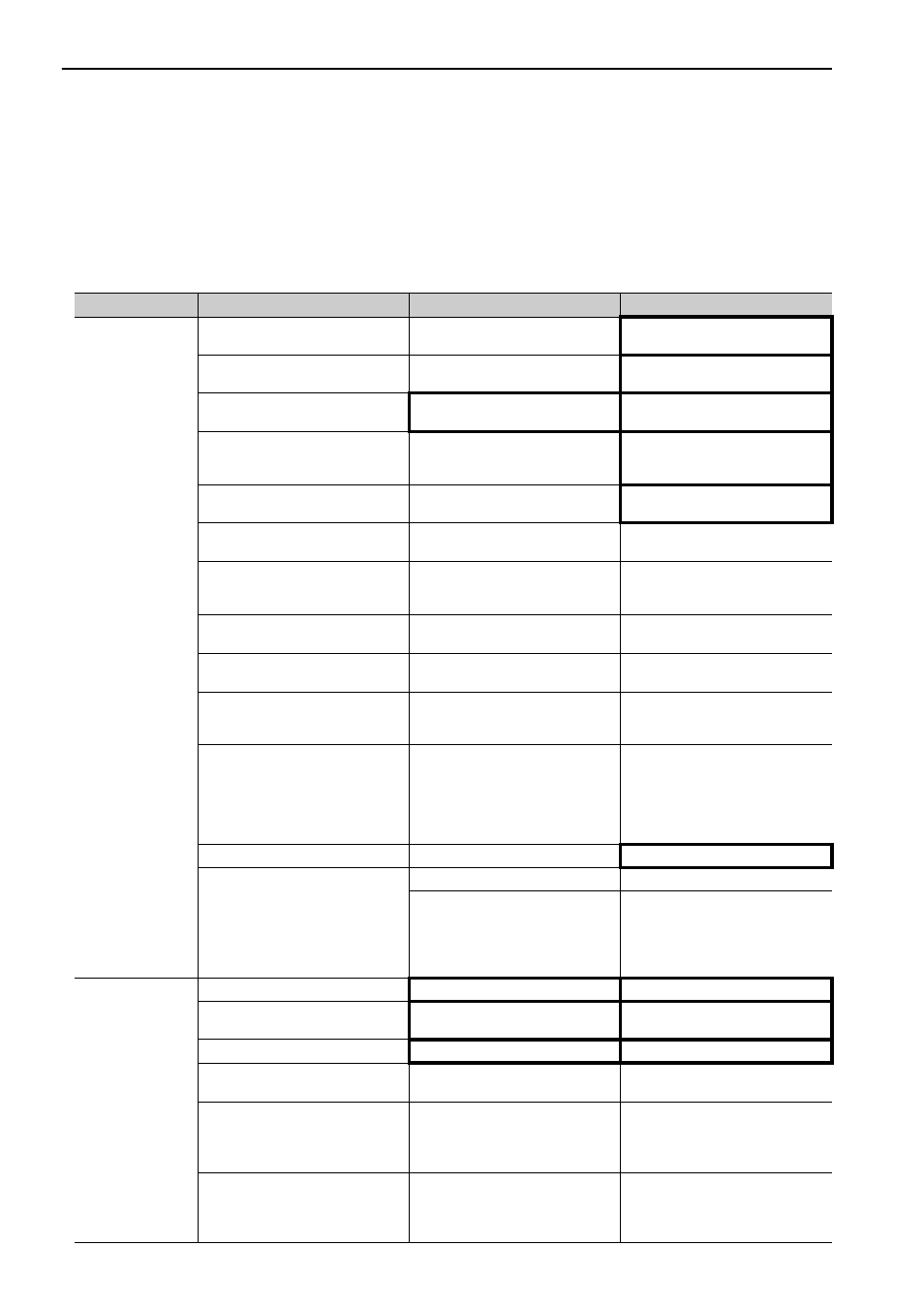
Troubleshooting for the malfunctions based on the operation and conditions of the servomotor is provided in
this section.
Be sure to turn OFF the servo system before troubleshooting items shown in bold lines in the table.
Problem
Probable Cause
Investigative Actions
Corrective Actions
Servomotor Does
Not Start
The control power supply is not
ON.
Check voltage between control
power terminals.
Correct the wiring.
The main circuit power supply is
not ON.
Check the voltage between main
circuit power terminals.
Correct the wiring.
Wiring of I/O signal connector CN1
is faulty or disconnected.
Check if the connector CN1 is prop-
erly inserted and connected.
Correct the connector CN1 connec-
tion.
Wiring for servomotor main circuit
cable or linear scale connection
cables is disconnected.
Check the wiring.
Correct the wiring.
Overloaded
Run under no load and check the
load status.
Reduce load or replace with larger
capacity servomotor.
Linear scale type differs from
parameter setting (Pn002.2).
Check the settings for parameter
Pn002.2.
Set parameter Pn002.2 to the linear
scale type being used.
Settings for the input signal selec-
tions (Pn50A, Pn50B and Pn511) is
incorrect.
Check the settings for parameters
Pn50A, Pn50B and Pn511.
Correct the settings for parameter
Pn50A, Pn50B and Pn511.
SV_ON command is not sent.
Check the command sent from the
host controller.
Send the SV_ON command.
SENS_ON command is not sent.
Check the command sent from the
host controller.
Send the command in the correct
SERVOPACK sequence.
The forward run prohibited (P-OT)
and reverse run prohibited (N-OT)
input signals are turned OFF.
Check P-OT or N-OT input signal.
Turn P-OT or N-OT input signal
ON.
The safety input signal (/HWBB1 or
/HWBB2) remains OFF.
Check the /HWBB1 and /HWBB2
input signal.
Set the /HWBB1 and /HWBB2
input signal to ON.
When not using the safety function,
mount the safety function’s jumper
connector (provided as an acces-
sory) on the CN8.
A SERVOPACK fault occurred.
−
Replace the SERVOPACK.
The polarity detection is not exe-
cuted.
Check the parameter Pn080.0.
Correct the setting of Pn080.0.
Check the SV_ON command.
• When using an incremental linear
scale, send the SV_ON command
from the host controller.
• When using an absolute linear
scale, execute Fn080.
Servomotor
Moves
Instantaneously,
and then Stops
Servomotor wiring is incorrect.
Check the wiring.
Correct the wiring.
Serial converter unit wiring is incor-
rect.
Check the wiring.
Correct the wiring.
Linear scale wiring is incorrect.
Check the wiring.
Correct the wiring.
Linear scale pitch (Pn282) is incor-
rect.
Check the setting of Pn282.
Correct the setting of Pn282.
Linear scale counting up direction
and servomotor coil assembly for-
ward direction do not agree.
Check the directions.
Change the setting of Pn080.1
(Motor Phase Selection).
Match the linear scale direction and
coil assembly direction.
Polarity detection is not performed
correctly.
Check if the value of Un004 (elec-
trical angle 2 from polarity origin)
at an arbitrary position is between
±10 degrees.
Correct the settings for the polarity
detection related parameter.