6 servopack model designation, Sgdv, 2r8 a 25 a – Yaskawa Sigma-5 User Manual: Design and Maintenance - Linear Motors MECHATROLINK-III Communications Reference User Manual
Page 40
1.6 SERVOPACK Model Designation
1-19
1
Outline
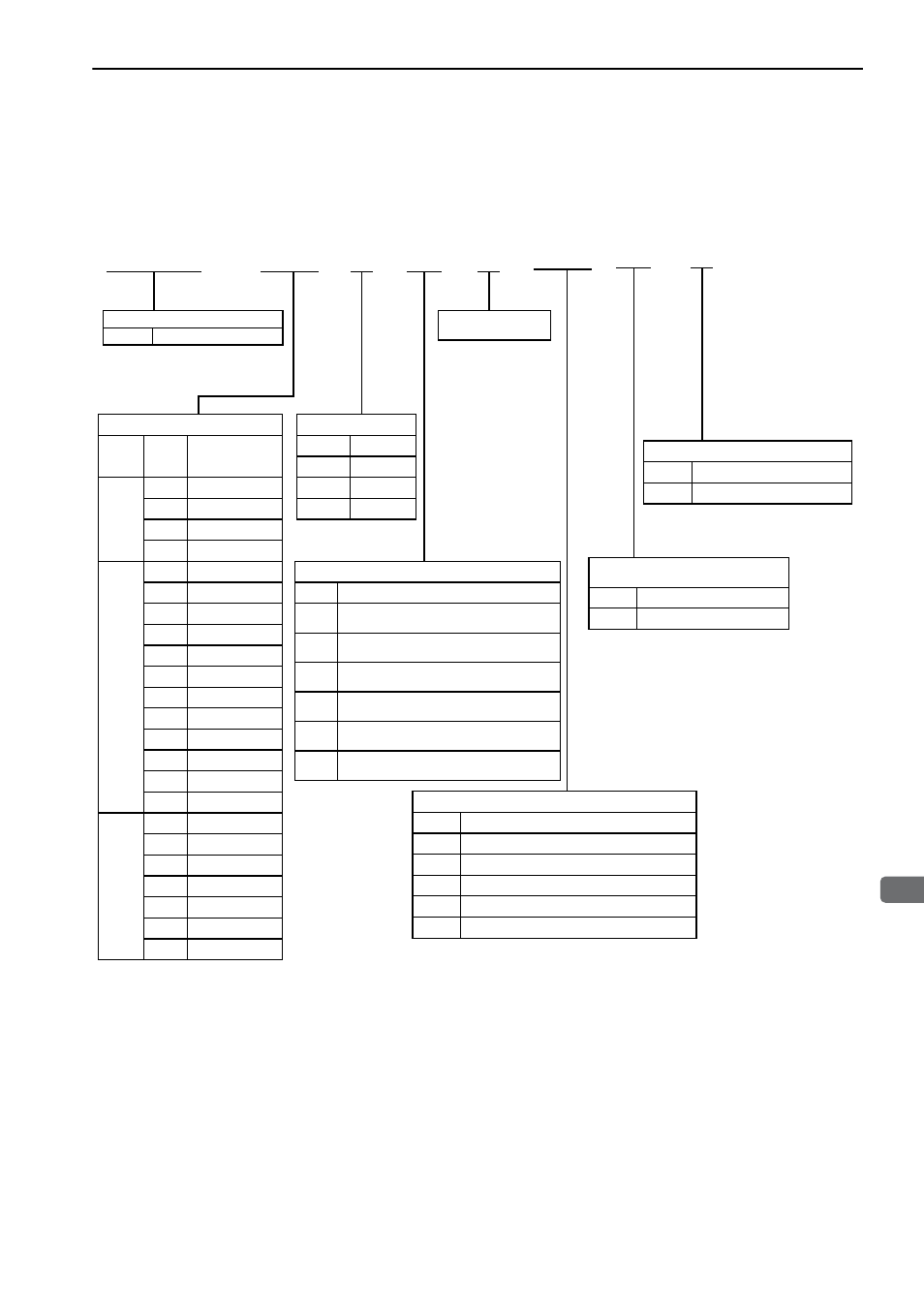
1.6 SERVOPACK Model Designation
This section shows SERVOPACK model designation.
∗1. These amplifiers can be powered with single or three-phase.
∗2. SGDV-550A and -260D are duct-ventilated types.
∗3. A resistor for the dynamic brake is not included. An external resistor for the dynamic brake can only be used with
400-V SERVOPACKs.
Note: If the option codes digits 8 to 13 are all zeros, they are omitted.
SGDV
Series
SGDV
Σ-V Series
1st + 2nd + 3rd digits: Current
Voltage Code
Max. Allowable
Motor Capacity
(kW)
100 V
R70
0.05
R90
0.1
2R1
0.2
2R8
0.4
200 V
R70
*1
0.05
R90
*1
0.1
1R6
*1
0.2
2R8
*1
0.4
3R8
0.5
5R5
*1
0.75
7R6
1
120
1.5
180
2
200
3
330
5
550
*2
7.5
400 V
1R9
0.5
3R5
1
5R4
1.5
8R4
2
120
3
170
5
260
*2
7.5
4th digit: Voltage
Code
Voltage
F
100 V
A
200 V
D
400 V
5th + 6th digits: Interface Specifications
Code
Interface
01
Analog voltage and pulse train refer-
ence, rotational servomotor
05
Analog voltage and pulse train refer-
ence, linear servomotor
11
MECHATROLINK-II communications
reference, rotational servomotor
15
MECHATROLINK-II communications
reference, linear servomotor
21
MECHATROLINK-III communications
reference, rotational servomotor
25
MECHATROLINK-III communications
reference, linear servomotor
11th + 12th digits: Software Specifi-
cation
Code Specification
00
Standard
–
7th digit: Design
Revision Order
1st + 2nd +
3rd digits
4th
digit
5th + 6th
digits
7th
digit
2R8 A 25 A
8th + 9th +
10th digits
000
8th + 9th + 10th digits: Hardware Specifications
Code
Specifications
000
Base-mounted (standard)
001
Rack-mounted
*2
002
Varnished
003
Rack-mounted
*2
and Varnished
020
Dynamic brake (DB)
*3
11th + 12th
digits
00
13th
digit
0
13th digit: Parameter Specification
Code Specification
0
Standard