Yaskawa Sigma-5 User Manual: Design and Maintenance - Linear Motors MECHATROLINK-III Communications Reference User Manual
Page 295
8 Troubleshooting
8-34
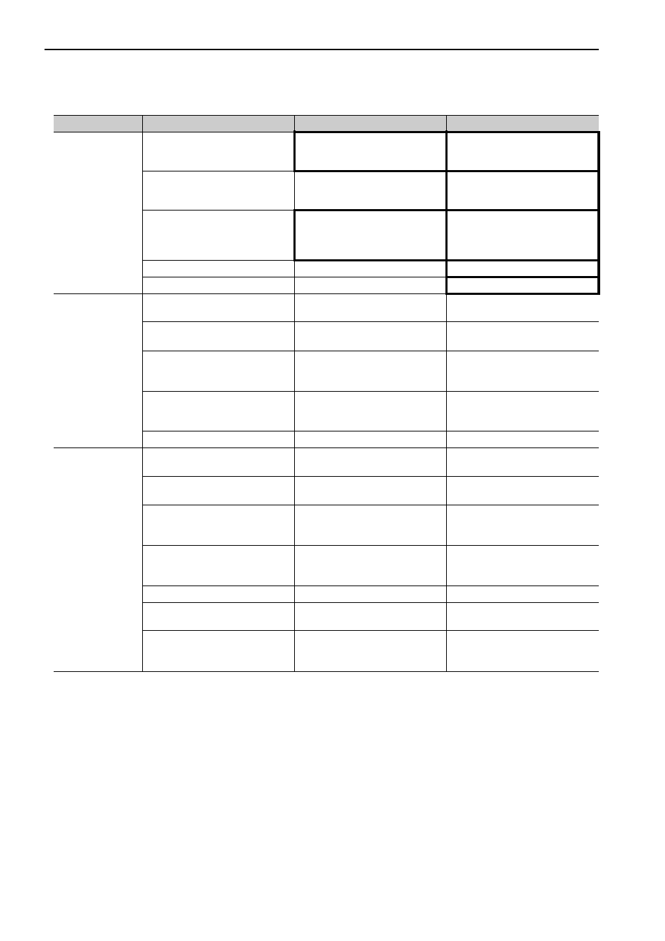
Abnormal Noise
from Servomotor
(cont’d)
The FG potential varies because of
influence from machines on the ser-
vomotor side, such as the welder.
Check if the machines are correctly
grounded.
Properly ground the machines to
separate from the linear scale FG.
SERVOPACK pulse counting error
due to noise interference
Check if there is noise interference
on the I/O signal line from the linear
scale.
Take measures against noise in the
linear scale wiring.
Excessive vibration and shock to
the linear scale
Check if vibration from the machine
occurred or linear scale installation
is incorrect (mounting surface accu-
racy and fixing method).
Reduce vibration from the machine,
or secure the linear scale installa-
tion.
Serial converter unit fault
−
Replace the serial converter unit.
A linear scale fault occurred.
−
Replace the linear scale.
Servomotor
Vibrates at
Frequency of
Approx. 200 to
400 Hz.
Unbalanced servo gains
Check to see if the servo gains have
been correctly adjusted.
Execute the advanced autotuning.
Speed loop gain value (Pn100) too
high.
Check the speed loop gain (Pn100).
Factory setting: Kv = 40.0 Hz
Reduce the speed loop gain
(Pn100).
Position loop gain value (Pn102)
too high.
Check the position loop gain
(Pn102).
Factory setting: Kp = 40.0/s
Reduce the position loop gain
(Pn102).
Incorrect speed loop integral time
constant (Pn101)
Check the speed loop integral time
constant (Pn101).
Factory setting: Ti = 20.0 ms
Correct the speed loop integral time
constant (Pn101).
Incorrect mass ratio (Pn103)
Check the mass ratio (Pn103).
Correct the mass ratio (Pn103).
High Motor Speed
Overshoot on
Starting and
Stopping
Unbalanced servo gains
Check to see if the servo gains have
been correctly adjusted.
Execute the advanced autotuning.
Speed loop gain value (Pn100) too
high
Check the speed loop gain (Pn100).
Factory setting: Kv = 40.0 Hz
Reduce the speed loop gain
(Pn100).
Position loop gain value (Pn102)
too high
Check the position loop gain
(Pn102).
Factory setting: Kp = 40.0/s
Reduce the position loop gain
(Pn102).
Incorrect speed loop integral time
constant (Pn101)
Check the speed loop integral time
constant (Pn101).
Factory setting: Ti = 20.0 ms
Correct the speed loop integral time
constant (Pn101).
Incorrect mass ratio data (Pn103)
Check the mass ratio (Pn103).
Correct the mass ratio (Pn103).
The force reference is saturated.
Check the force reference wave
form.
Use the mode switch function.
The force limit (Pn483, Pn484) is
set to the initial value.
Initial value of force limit:
Pn483 = 30%
Pn484 = 30%
Set a appropriate value for Pn483
and Pn484 (Force Limit).
(cont’d)
Problem
Probable Cause
Investigative Actions
Corrective Actions