Yaskawa Sigma-5 User Manual: Design and Maintenance - Linear Motors MECHATROLINK-III Communications Reference User Manual
Page 307
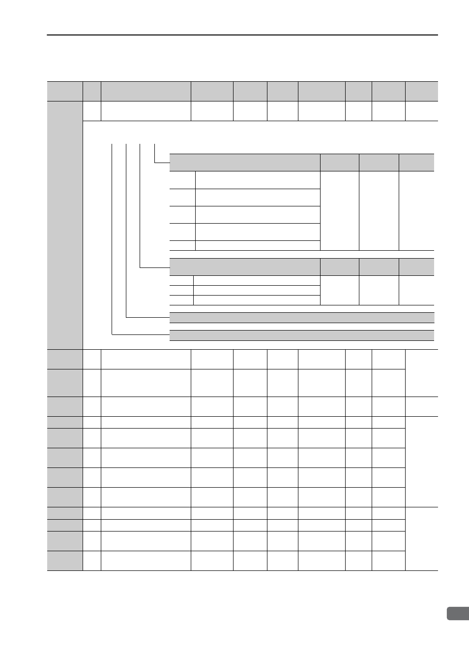
9.1 List of Parameters
9-9
9
Ap
pend
ix
Pn10B
2
Application Function for
Gain Select Switch
0000 to 5334
−
0000
−
−
−
−
Pn10C
2
Mode Switch
(force reference)
0 to 800
1%
200
Immediately
Tuning
−
5.9.2
Pn10F
2
Mode Switch
(position error)
0 to 10000
1
reference
unit
0
Immediately
Tuning
−
Pn11F
2
Position Integral Time
Constant
0 to 50000
0.1 ms
0
Immediately
Tuning
−
5.9.4
Pn121
2
Friction Compensation Gain
10 to 1000
1%
100
Immediately
Tuning
−
5.8.2
Pn122
2
2nd Gain for Friction
Compensation
10 to 1000
1%
100
Immediately
Tuning
−
Pn123
2
Friction Compensation
Coefficient
0 to 100
1%
0
Immediately
Tuning
−
Pn124
2
Friction Compensation
Frequency Correction
-10000 to
10000
0.1 Hz
0
Immediately
Tuning
−
Pn125
2
Friction Compensation
Gain Correction
1 to 1000
1%
100
Immediately
Tuning
−
Pn131
2
Gain Switching Time 1
0 to 65535
1 ms
0
Immediately
Tuning
−
5.8.1
Pn132
2
Gain Switching Time 2
0 to 65535
1 ms
0
Immediately
Tuning
−
Pn135
2
Gain Switching
Waiting Time 1
0 to 65535
1 ms
0
Immediately
Tuning
−
Pn136
2
Gain Switching
Waiting Time 2
0 to 65535
1 ms
0
Immediately
Tuning
−
(cont’d)
Parameter
No.
Size
Name
Setting
Range
Units
Factory
Setting
When
Enabled
Classi-
fication
Profile
Reference
Section
Mode Switch Selection
When
Enabled
Classification
Reference
Section
0
Uses internal force reference as the condition
(Level setting: Pn10C).
Immediately
Setup
5.9.2
1
Uses speed reference as the condition (Level
setting: Pn181).
2
Uses acceleration as the condition (Level setting:
Pn182).
3
Uses position error as the condition (Level setting:
Pn10F).
4
No mode switch function available.
Speed Loop Control Method
When
Enabled
Classification
Reference
Section
0
PI control
After restart
Setup
−
1
I-P control
2 to 3
Reserved (Do not change.)
Reserved (Do not change.)
Reserved (Do not change.)
4th 3rd 2nd 1st
digit digit digit digit
n.