3 monitoring operation during adjustment, 1) connector cn5 for analog monitor, 2) monitor signal – Yaskawa Sigma-5 User Manual: Design and Maintenance - Linear Motors MECHATROLINK-III Communications Reference User Manual
Page 155: M-iii, 48 and 65, Connection example
5.1 Type of Adjustments and Basic Adjustment Procedure
5-5
5
Adjustments
5.1.3 Monitoring Operation during Adjustment
Check the operating status of the machine and signal waveform when adjusting the servo gain. Connect a mea-
suring instrument, such as a memory recorder, to connector CN5 analog monitor connector on the SERVO-
PACK to monitor analog signal waveform.
The settings and parameters for monitoring analog signals are described in the following sections.
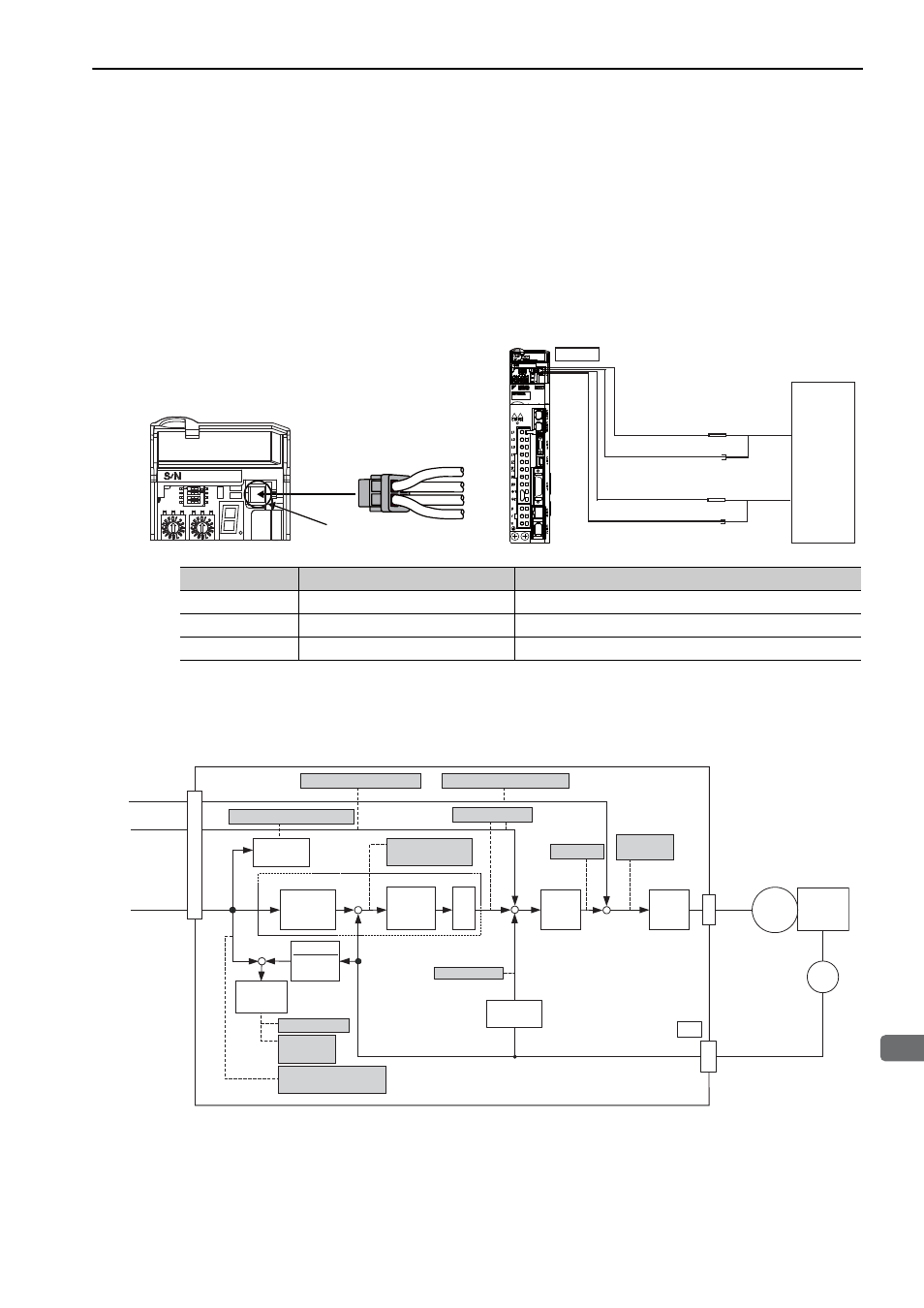
(1) Connector CN5 for Analog Monitor
To monitor analog signals, connect a measuring instrument with cable (JZSP-CA01-E) to the connector CN5.
(2) Monitor Signal
The shaded parts in the following diagram indicate analog output signals that can be monitored.
Line Color
Signal Name
Factory Setting
White
Analog monitor 1
Force reference: 1 V/100% rated force
Red
Analog monitor 2
Motor speed: 1 V/1000 mm/s
Black (2 lines)
GND
Analog monitor GND: 0 V
CN5
JZSP-CA01-E
White
Red
Black
Black
Probe GND
Measuring
Probe
Probe GND
Measuring
Probe
White
Red
Black
Black
CN5
Measuring
Instrument*
Connection Example
∗ Measuring instrument is not included.
M-III
ENC
CN2
(U/V/W)
−
+
+
−
+
+
+
Force
reference
Speed
reference
Position
reference
−
+
1
SERVOPACK
Speed feedforward
Position reference speed
Position
amplifier error
Motor speed
Speed reference
Active gain
Force
reference
Speed
conversion
Electronic
gear
Speed
loop
Current
loop
Electronic
gear
Position loop
Force feedforward
Error
counter
Error
counter
Load
M
Kp
Position error
Positioning
completed
Completion of position
reference
Speed
conversion
48 and 65