Yaskawa Sigma-5 User Manual: Design and Maintenance - Linear Motors MECHATROLINK-III Communications Reference User Manual
Page 302
9 Appendix
9.1.2 Parameters
9-4
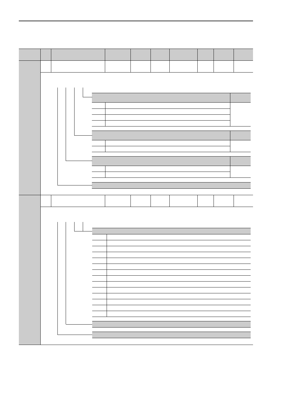
Pn002
2
Application Function Select
Switch 2
0000 to 4113
−
0011
After restart
Setup
−
−
Pn006
2
Application Function Select
Switch 6
0000 to 005F
−
0002
Immediately
Setup
−
5.1.3
∗1. For details, refer to
Σ
-V Series User’s Manual MECHATROLINK-III Standard Servo Profile Commands (No.: SIEP
S800000 63).
(cont’d)
Parameter
No.
Size
Name
Setting
Range
Units
Factory
Setting
When
Enabled
Classi-
fication
Profile
Reference
Section
MECHATROLINK Command Position and Speed Control Option
Reference
Section
0
Reserved (Do not set.)
*1
1
TLIM operates as the force limit values.
2
Reserved (Do not set.)
3
Reserved (Do not set.)
Force Control Option
Reference
Section
0
Reserved (Do not set.)
*1
1
VLIM operates as the speed limit value.
Absolute Linear Scale Usage
Reference
Section
0
Uses absolute linear scale as an absolute linear scale.
4.7
1
Uses absolute linear scale as an incremental linear scale.
Reserved (Do not change.)
4th 3rd 2nd 1st
digit digit digit digit
n.
Analog Monitor 1 Signal Selection
00
Motor moving speed (1 V / 1000 mm/s)
01
Speed reference (1 V / 1000 mm/s)
02
Force reference (1 V/100% rated force)
03
Position error (0.05 V/1 reference unit)
04
Position amplifier error (after electronic gears) (0.05 V/ 1 linear scale pulse unit)
05
Position reference speed (1 V / 1000 mm/s)
06
Reserved (Do not use.)
07
Reserved (Do not use.)
08
Positioning completion (positioning completed: 5 V, positioning not completed: 0 V)
09
Speed feedforward (1 V / 1000 mm/s)
0A
Force feedforward (1 V/100% rated force)
0B
Active gain (1st gain: 1 V, 2nd gain: 2 V)
0C
Completion of position reference (completed: 5 V, not completed: 0 V)
0D
Reserved (Do not use.)
Reserved (Do not change.)
Reserved (Do not change.)
4th 3rd 2nd 1st
digit digit digit digit
n.