4 connecting the external setpoint specification – SMA SC 500CP-10-JP Installation Manual User Manual
Page 62
12 Cable Connection of External Devices and Connections in the Interface Cabinet
SMA Solar Technology AG
62
SCCP-JP-IA-A4-en-12
Installation Manual
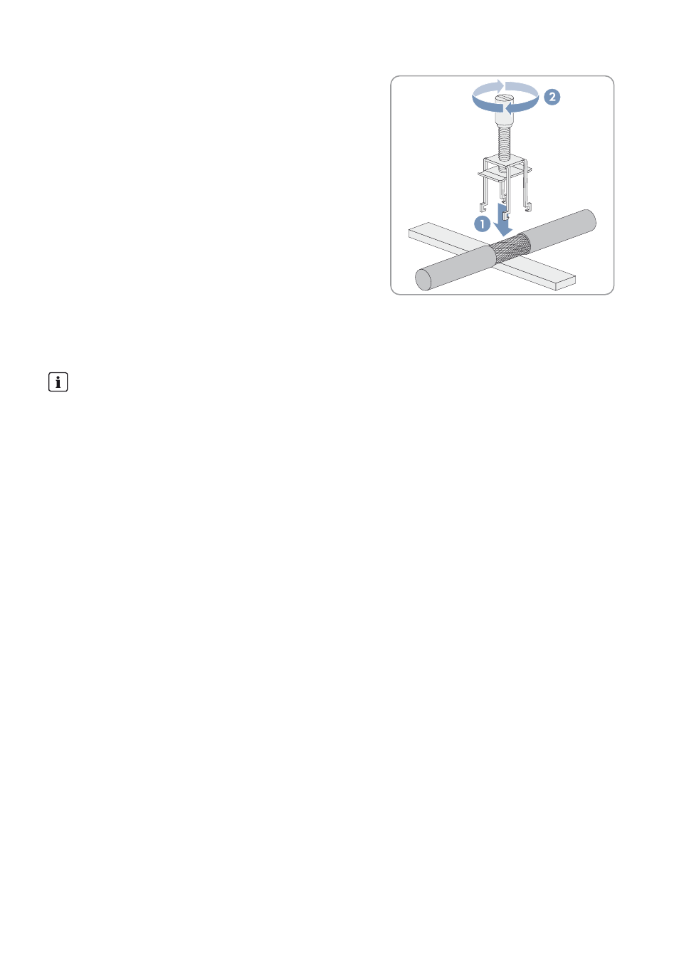
4. Press the shield clamping saddle down onto the shield of the
stripped cable until it snaps into place and fasten hand-tight.
5. Attach the cable to the cable support rail using a cable tie. This will ensure that the cable cannot be pulled out
inadvertently.
12.3.4 Connecting the External Setpoint Specification
You will find further information on how the external setpoint specification works in the Sunny Central operating manual.
Cable requirement:
☐ The cable must be shielded.
Requirement:
☐ The Sunny Central must be disconnected (see Section 14 "Disconnecting the Sunny Central", page 69).
Procedure:
1. Insert the external setpoint cable in the interface cabinet (see Section 12.2 "Leading the Cables into the Interface
2. Connect the cable in accordance with the circuit diagram (see Section 12.3.1 "Connecting the Cables to the
Connecting Terminal Plate", page 59).
3. Remove the shield clamping saddle from the busbar.
Signal transmission
External setpoints for reactive power and active power are normally specified by the grid operator, e.g. via a ripple
control signal. The Power Reducer Box or the Power Plant Controller receives the setpoints from the ripple control
receiver and sends these to the Sunny Central. The Sunny Central applies the specifications of the grid operator and
feeds, for example, a specified amount of reactive power into the utility grid. Ask your grid operator which type of
signal transmission is used.
If these setpoints are not transmitted via the Power Reducer Box, there are terminals located in the Sunny Central
for connecting the external setpoints. The Sunny Central processes analog standard signals of 4 mA to 20 mA.