2 dc connection with dc fuse option, 1 cable and terminal lug requirements – SMA SC 500CP-10-JP Installation Manual User Manual
Page 45
SMA Solar Technology AG
10 DC Connection
Installation Manual
SCCP-JP-IA-A4-en-12
45
10.2 DC Connection with DC Fuse Option
10.2.1 Cable and Terminal Lug Requirements
Cables:
☐ Use copper or aluminum cables only.
☐ Maximum cable cross-section: 400 mm
2
Terminal lugs:
☐ Use tin-plated terminal lugs only.
☐ Only use the nuts, screws and washers included in the scope of delivery for the connection.
☐ Always connect two-hole terminal lugs with two screws.
☐ The terminal lugs must be designed for temperatures of at least +95°C.
☐ The width of the terminal lugs must exceed the washer diameter (32 mm). This will ensure that the defined torques
are effective over the whole surface.
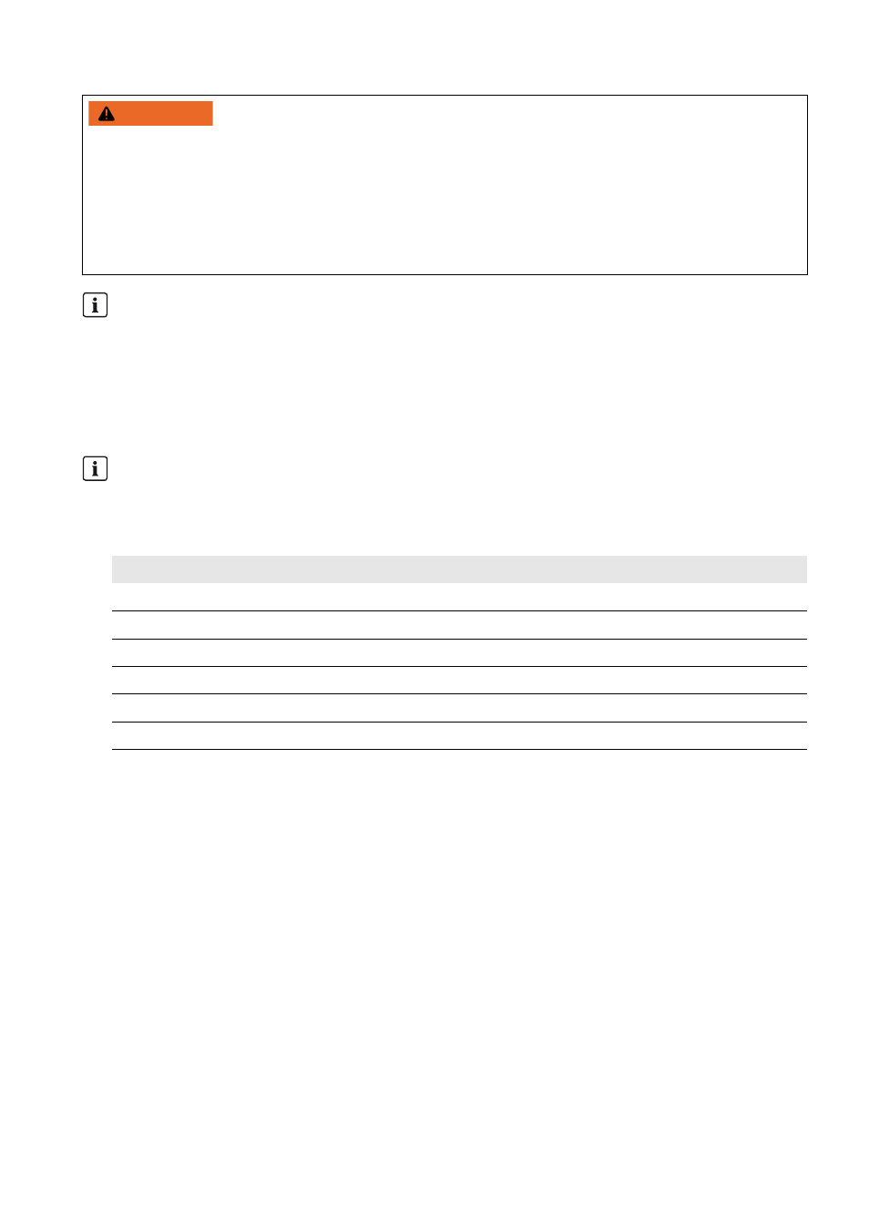
:$51,1*
Risk of fire due to failure to observe torque specifications on live bolted connections
Failure to follow the specified torques reduces the ampacity of live bolted connections so that the contact resistances
increase. This can cause components to overheat and catch fire.
• Ensure that live bolted connections are always tightened with the exact torque specified in this document.
• When working on the device, use suitable tools only.
• Avoid repeated tightening of live bolted connections as this may result in inadmissibly high torques.
DC-side disconnection
The DC main distributions and DC sub-distributions should be equipped with circuit breakers. Circuit breakers
enable trouble-free DC-side disconnection of the inverter.
Reduced DC input currents
The DC inputs are fused with LV/HRC size-3 fuses.
Thermal stress and fluctuating loads on the Sunny Central result in a screening factor of 0.7. This screening factor
must be taken into account in the DC cable design.
Fusing
Reduced DC current
125 A
87.5 A
160 A
112.0 A
200 A
140.0 A
250 A
175.0 A
315 A
220.5 A
400 A
280.0 A