SMA SC 500CP-10-JP Installation Manual User Manual
Page 26
6 Preparation for Installation
SMA Solar Technology AG
26
SCCP-JP-IA-A4-en-12
Installation Manual
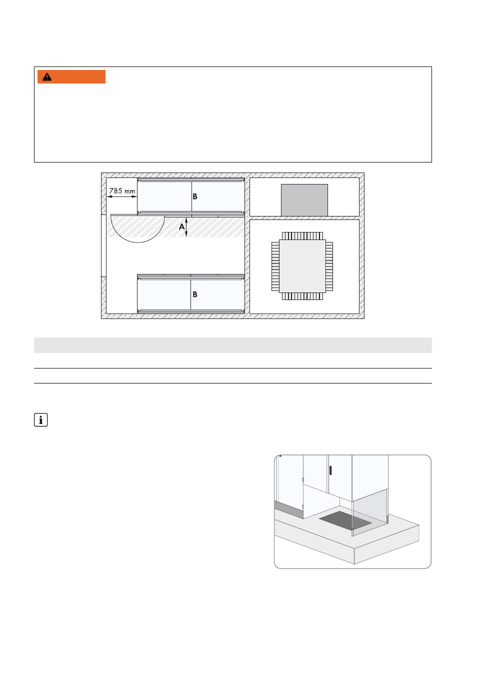
Minimum Clearances for Two Sunny Central Inverters Installed in Electrical Equipment Rooms
Figure 12: Minimum clearances for two Sunny Central inverters in an electrical equipment room
6.1.5 Requirements for Foundation and Cable Arrangement
☐ Openings for the cables must be located in the foundation
underneath the interface cabinet.
☐ Empty conduits for the cables must be laid under the foundation.
☐ The data cables must be kept separate from the AC and DC
cables.
☐ There must be sufficient space available to lay the cables properly.
:$51,1*
Danger due to blocked escape route
Opening the doors of two Sunny Central inverters located opposite each other blocks the escape route. It is imperative
that the escape route is freely accessible at all times. Make sure the minimum passage width of the route meets local
standards. In Germany, the minimum passage width is 500 mm.
• Only open the door of one Sunny Central at a time.
• Comply with local requirements concerning minimum passage widths.
Position
Designation
A
Minimum passage width
B
Sunny Central
Laying the cables
This manual does not specify at what stage the cables are to be laid in the foundation. The stage at which the cables
are laid must be determined individually for each PV system.