SMA SC 500CP-10-JP Installation Manual User Manual
Page 60
12 Cable Connection of External Devices and Connections in the Interface Cabinet
SMA Solar Technology AG
60
SCCP-JP-IA-A4-en-12
Installation Manual
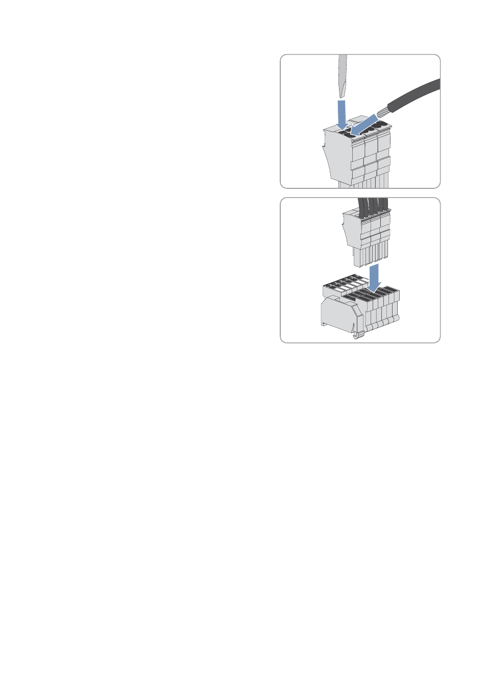
• Insert the screwdriver in the square opening of the connection
plug. This will release the opening of the connection plug for
the insulated conductors.
• Insert the insulated conductors of the cable in the connection
plug as shown in the circuit diagram.
• Remove the screwdriver from the connection plug.
• Plug the connection plug into the base terminal.
12.3.2 Connecting the Data Cables of the Sunny String-Monitor
The data cable for the RS485 communication and the +55 V
DC
voltage supply links the Sunny String-Monitor with the
Sunny Central.
For an optimum voltage supply, SMA Solar Technology AG recommends connecting two insulated conductors with a
cross section of 0.5 mm
2
each to one voltage supply terminal. You can connect two insulated conductors to one terminal
for the GND_EXT signal in just the same way.
Recommended cable type: Li2YCYv (TP) 4 x 2 x 0.5 mm
2
.
Cable requirement:
☐ The voltage supply and the communication connection must be combined in one cable.
☐ The cable must be shielded.
Requirement:
☐ The Sunny Central must be disconnected (see Section 14 "Disconnecting the Sunny Central", page 69).
Procedure:
1. Insert the Sunny String-Monitor cable in the interface cabinet (see Section 12.2 "Leading the Cables into the
2. Connect the cable to the surge arrester in accordance with the circuit diagram (see Section 12.3.1 "Connecting the
Cables to the Connecting Terminal Plate", page 59).
3. Remove the shield clamping saddle from the busbar.