SMA SC 500CP-10-JP Installation Manual User Manual
Page 27
SMA Solar Technology AG
6 Preparation for Installation
Installation Manual
SCCP-JP-IA-A4-en-12
27
6.1.6 Requirements for Cable Routing between MV Transformer and
Sunny Central
☐ The line conductors must be bundled in the three-phase system.
☐ Between the MV transformer and the Sunny Central there must be three separate cable routes for the AC cables,
e.g. cable channels.
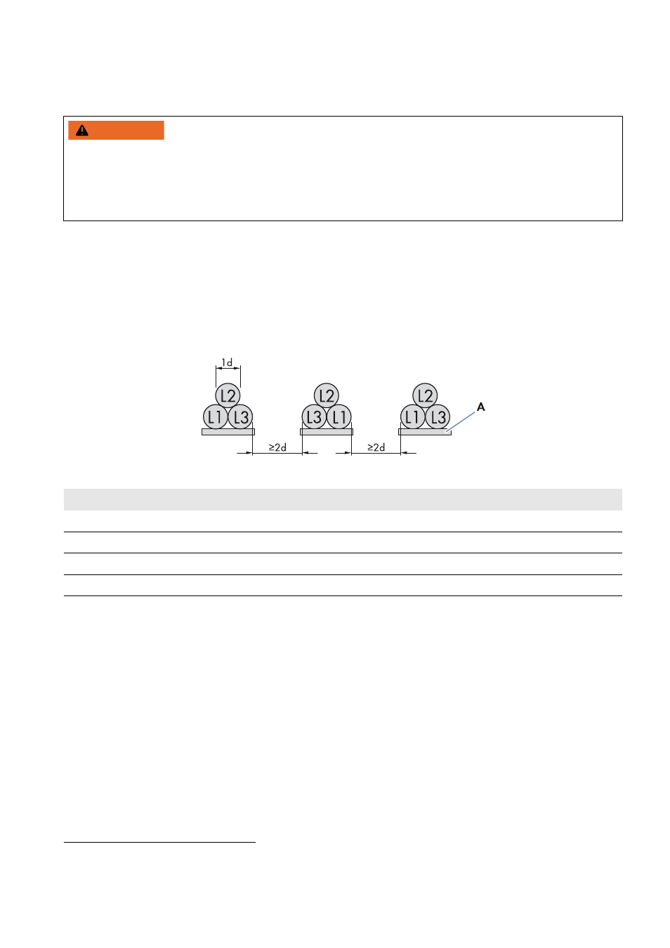
☐ A line conductor L1, L2 and L3 must be laid in each cable channel. Ensure that the distance between the cable
bundles is at least double that of the diameter of a cable. This will prevent current imbalances. Furthermore, it is
recommended to execute cabling between inverter and transformer directly on a grounding strap. This measure
further reduces electromagnetic influences.*
Figure 13: Arrangement of AC cables with three cables per line conductor (example)
:$51,1*
Risk of fire due to overheating of cables
Differing cable lengths cause overheating.
• All line conductors from the Sunny Central to the MV transformer must be of the same length.
• The cable length between the connection points must not exceed 15 m.
* For further information, see the Technical Information "Cable Set ‒ Requirements for and Laying of Cables between Sunny Central CP and
Transformer Compact Station" at www.SMA-Solar.com.
Position
Designation
L1
Line conductor L1
L2
Line conductor L2
L3
Line conductor L3
A
Grounding strap