3 disassembling the panels on the connection area – SMA SC 500CP-10-JP Installation Manual User Manual
Page 37
SMA Solar Technology AG
8 Installing the Sunny Central
Installation Manual
SCCP-JP-IA-A4-en-12
37
8.3 Disassembling the Panels on the Connection Area
The panels are located at the bottom of the interface cabinet of the Sunny Central.
Procedure:
1. Remove the panel screws using a Torx screwdriver (T30).
2. Carefully remove the front panel of the connection area. Pull the panel forwards by 80 mm to 100 mm.
3. Detach the grounding conductor from the rear side of the panel.
4. Remove the panels.
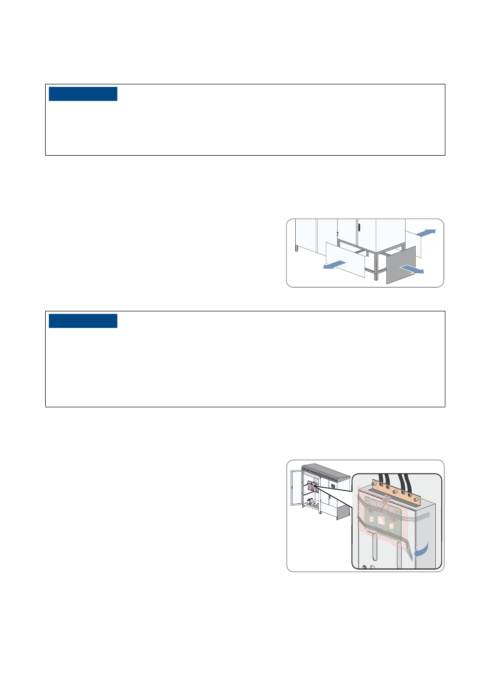
8.4 Removing the Transport Lock from the Inverter Cabinet
Depending on the production version, the three inverter bridges are secured for transport with ESD bubble wrap.
Procedure:
1. Open the inverter cabinet.
2. Remove the bubble wrap from each of the three inverter bridges.
Be sure to observe all ESD protection measures.
3. Close the inverter cabinet.
/05*$&
Property damage due to rupture of grounding conductors
The panels are connected to the Sunny Central via grounding conductors. If the panels are not removed correctly,
the grounding conductors may be pulled out.
• Take care not to damage the grounding conductors when disassembling the panels.
/05*$&
Damage to electronic components due to electrostatic discharge
Electrostatic discharge can destroy components.
• When working on the Sunny Central or handling assemblies, observe the ESD safety regulations and wear safety
gloves.
• Discharge electrostatic charge by touching uncoated, grounded enclosure parts (e.g. at grounding connection on
the doors). Only then is it safe to touch electronic components.