1 measur ing w o rk piece misalignment – HEIDENHAIN TNC 426B (280 472) Touch Probe Cycles User Manual
Page 48
36
3 Touch Probe Cycles for Automatic Workpiece Inspection
3.1 Measur
ing W
o
rk
piece Misalignment
U
U
U
U
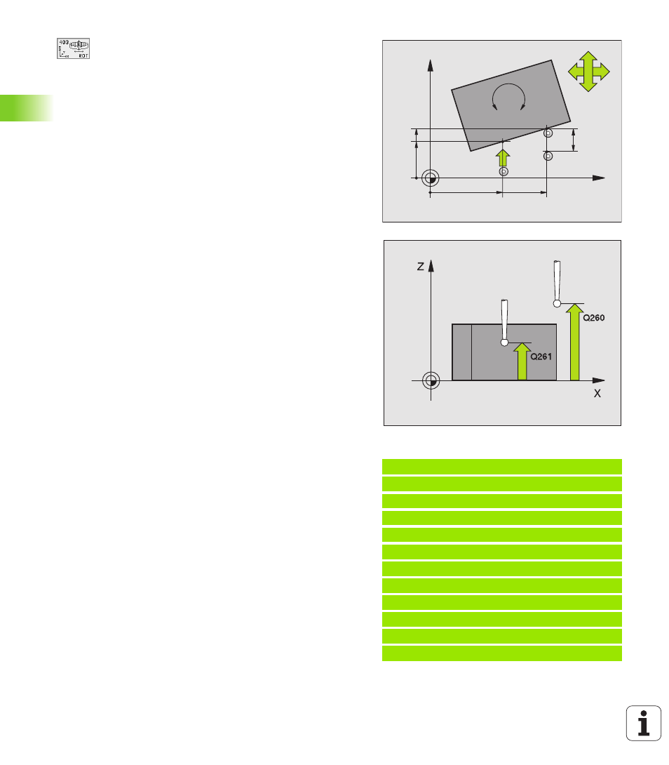
First measuring point in the 1st axis
Q263
(absolute): coordinate of the first touch point in the
reference axis of the working plane.
U
U
U
U
First measuring point in the 2nd axis
Q264
(absolute): coordinate of the first touch point in the
minor axis of the working plane.
U
U
U
U
Second measuring point in the 1st axis
Q265
(absolute): coordinate of the second touch point in the
reference axis of the working plane
U
U
U
U
Second measuring point in the 2nd axis
Q266
(absolute): coordinate of the second touch point in the
minor axis of the working plane
U
U
U
U
Measuring axis
Q272: axis in which the measurement
is to be made:
1: Reference axis = measuring axis
2: Minor axis = measuring axis
3: Touch probe axis = measuring axis
U
U
U
U
Traverse direction 1
Q267: direction in which the
probe is to approach the workpiece:
-1: Negative traverse direction
+1: Positive traverse direction
U
U
U
U
Measuring height in the touch probe axis
Q261
(absolute): coordinate of the ball tip center (= touch
point) in the touch probe axis in which the
measurement is to be made.
U
U
U
U
Setup clearance
Q320 (incremental): additional
distance between measuring point and ball tip. Q320
is added to MP6140.
U
U
U
U
Clearance height
Q260 (absolute): coordinate in the
touch probe axis at which no collision between tool
and workpiece (fixtures) can occur.
U
U
U
U
Traversing to clearance height
Q301: definition of
how the touch probe is to move between the
measuring points:
0: Move at measuring height between measuring
points
1: Move at clearance height between measuring
points
U
U
U
U
Axis for compensation motion
Q312: assignment of
the rotary axis in which the TNC is to compensate the
measured misalignment:
4: Compensate misalignment with rotary axis A
5: Compensate misalignment with rotary axis B
6: Compensate misalignment with rotary axis C
Example: NC blocks
5 TCH PROBE 403 ROT IN C-AXIS
Q263=+0 ;1ST POINT 1ST AXIS
Q264=+0 ;1ST POINT 2ND AXIS
Q265=+20 ;2ND POINT 1ST AXIS
Q266=+30 ;2ND POINT 2ND AXIS
Q272=1 ;MEASURING AXIS
Q267=+1 ;TRAVERSE DIRECTION
Q261=-5 ;MEASURING HEIGHT
Q320=0 ;SET-UP CLEARANCE
Q260=+20 ;CLEARANCE HEIGHT
Q301=0 ;TRAVERSE TO CLEAR HEIGHT
Q312=6 ;COMPENSATION AXIS
X
Y
Q266
Q264
Q263
Q272=1
Q265
Q272=2
+
–
–
+
Q267
MP6140
+
Q320
A
B
C