Measure plane (touch probe cycle 431, iso: g431), 3 a u to matic w o rk piece measur ement – HEIDENHAIN TNC 426B (280 472) Touch Probe Cycles User Manual
Page 109
HEIDENHAIN TNC 426, TNC 430
97
3.3 A
u
to
matic W
o
rk
piece Measur
ement
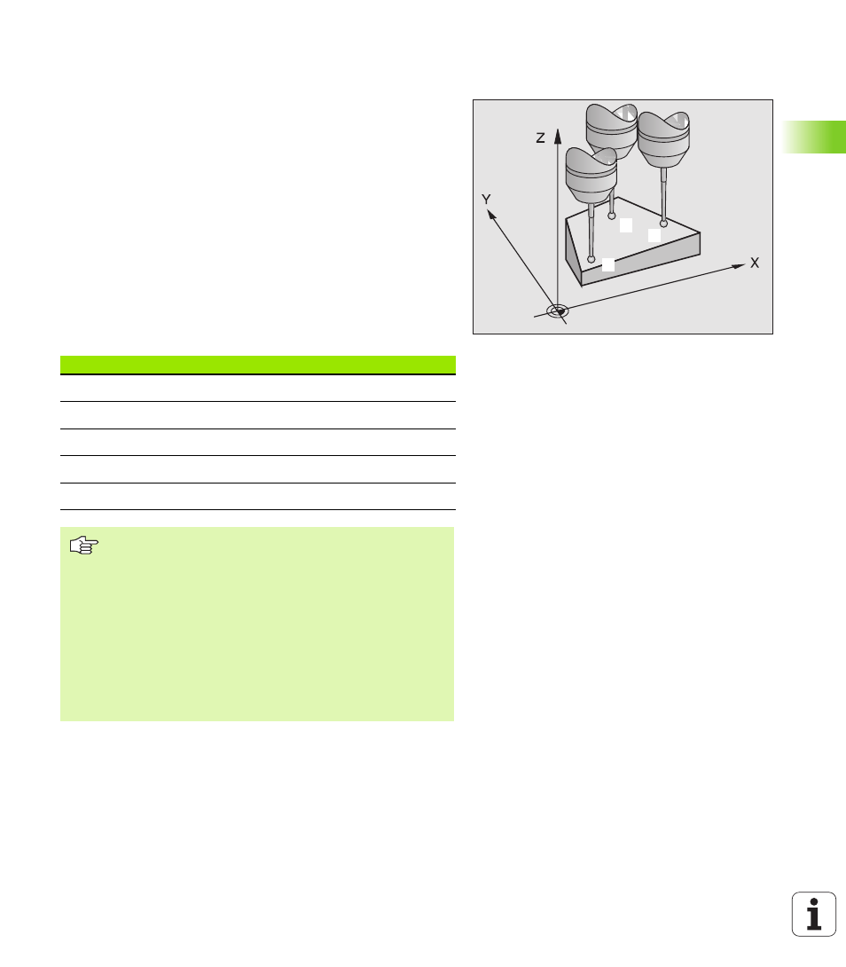
MEASURE PLANE (touch probe cycle 431,
ISO: G431)
Touch probe cycle 431 finds the angle of a plane by measuring three
points. It saves the measured values in system parameters.
1
Following the positioning logic (see “Running touch probe cycles”
on page 7), the TNC positions the touch probe at rapid traverse
(value from MP6150 or MP6361) to the programmed starting point
1
and measures the first touch point of the plane. The TNC offsets
the touch probe by the safety clearance in the direction opposite
to the direction of probing.
2
The touch probe returns to the clearance height and then moves in
the working plane to starting point
2
and measures the actual value
of the second touch point of the plane.
3
The touch probe returns to the clearance height and then moves in
the working plane to starting point
3
and measures the actual value
of the third touch point.
4
Finally the TNC returns the touch probe to the clearance height and
saves the measured angle values in the following Q parameters:
2
3
1
Parameter number
Meaning
Q158
Angle of the A axis
Q159
Angle of the B axis
Q170
Rotation about the A axis
Q171
Rotation about the B axis
Q172
Rotation about the C axis
Before programming, note the following:
Before a cycle definition you must have programmed a
tool call to define the touch probe axis.
For the TNC to be able to calculate the angular values, the
three measuring points must not be positioned on one
straight line.
As of NC software 280 476-12, parameters Q170 to Q172
find the angle of the rotary axes that are needed in the
“tilted working plane with spatial angle” function. With the
first two measuring points you also specify the direction of
the reference axis when tilting the working plane.