Calibrate the effective radius, 2 calibr a ting a t ouc h t rigg e r pr obe – HEIDENHAIN TNC 426B (280 472) Touch Probe Cycles User Manual
Page 26
14
2 Touch Probe Cycles in the Manual and Electronic Handwheel Modes
2.2 Calibr
a
ting a T
ouc
h T
rigg
e
r Pr
obe
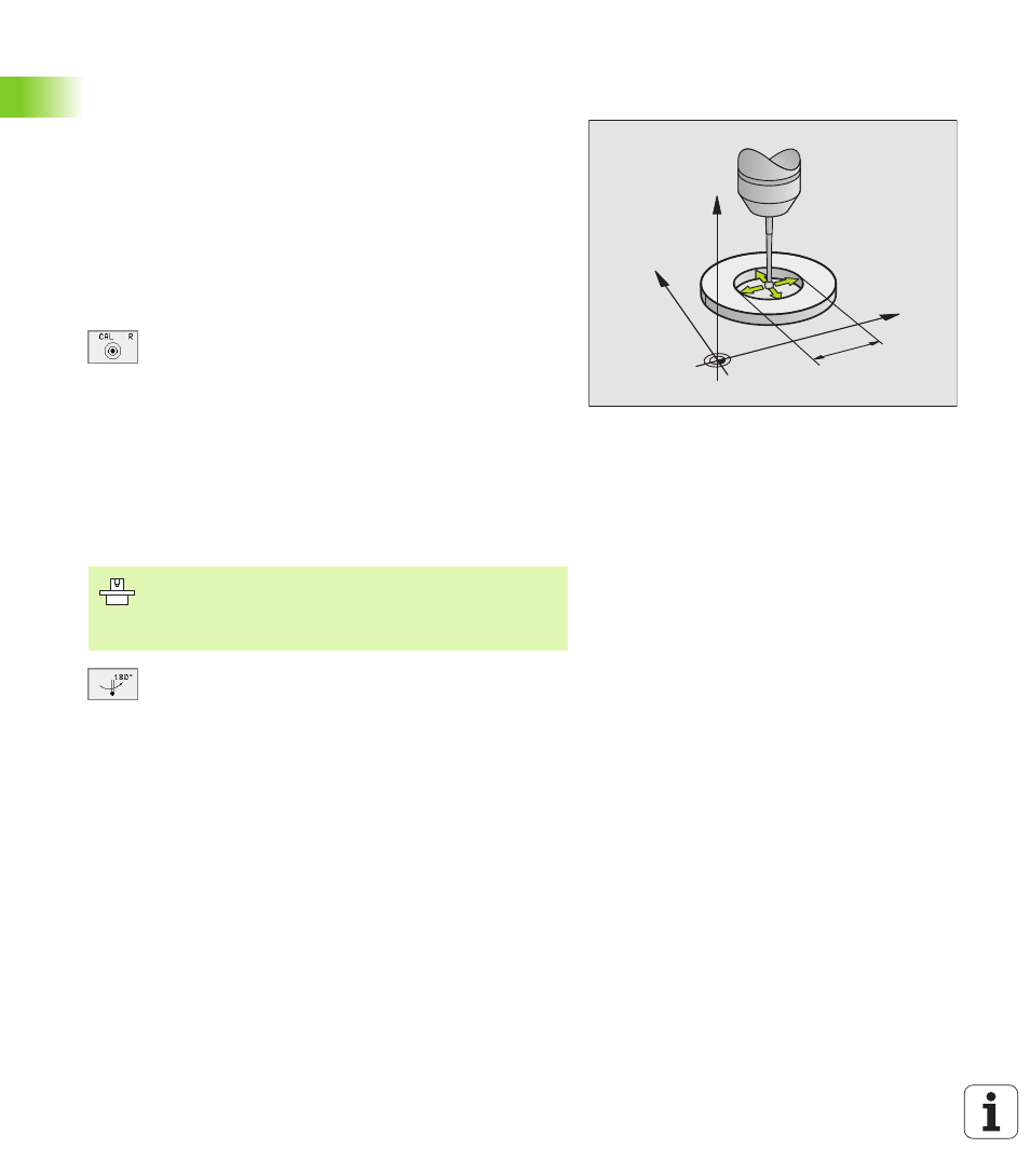
Calibrating the effective radius and
compensating center misalignment
After the touch probe is inserted it normally needs to be aligned
exactly with the spindle axis. The misalignment is measured with this
calibration function and compensated electronically.
For this operation the TNC rotates the 3-D touch probe by 180°. The
rotation is initiated by a miscellaneous function that is set by the
machine tool builder in machine parameter 6160.
The center misalignment is measured after the effective ball tip radius
is calibrated.
U
U
U
U
In the Manual Operation mode, position the ball tip in the bore of the
ring gauge.
U
U
U
U
To select the calibration function for the ball-tip radius
and the touch probe center misalignment, press the
CAL R soft key.
U
U
U
U
Select the tool axis and enter the radius of the ring
gauge.
U
U
U
U
To probe the workpiece, press the machine START
button four times. The touch probe contacts a
position on the bore in each axis direction and
calculates the effective ball-tip radius.
U
U
U
U
If you want to terminate the calibration function at this
point, press the ENDE soft key.
U
U
U
U
If you want to determine the ball-tip center
misalignment, press the180° soft key. The TNC
rotates the touch probe by 180°.
U
U
U
U
To probe the workpiece, press the machine START
button four times. The touch probe contacts a
position on the bore in each axis direction and
calculates the ball-tip center misalignment.
Y
X
Z
10
In order to be able to determine ball-tip center
misalignment, the TNC needs to be specially prepared by
the machine manufacturer. The machine tool manual
provides further information.