1 measur ing w o rk piece misalignment – HEIDENHAIN TNC 426B (280 472) Touch Probe Cycles User Manual
Page 44
32
3 Touch Probe Cycles for Automatic Workpiece Inspection
3.1 Measur
ing W
o
rk
piece Misalignment
U
U
U
U
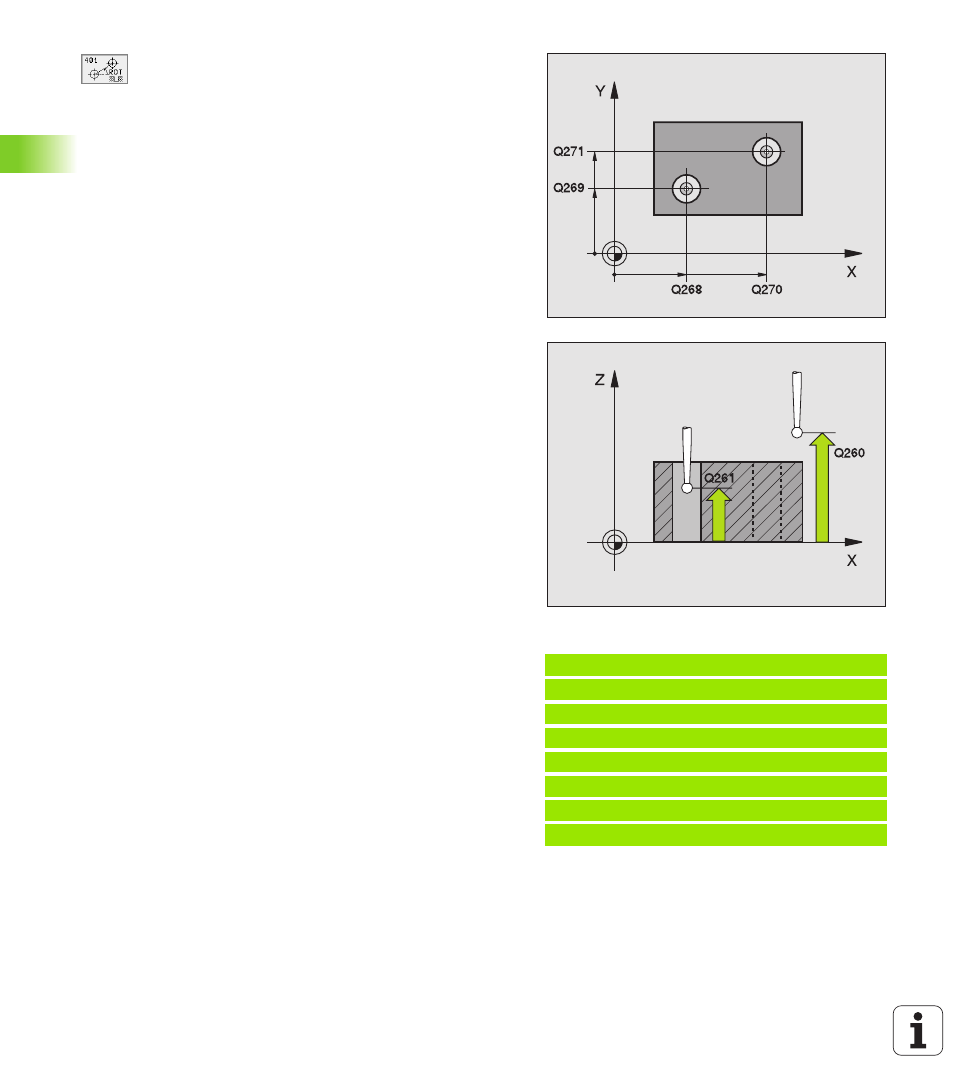
First hole: Center in 1st axis
Q268 (absolute):
center of the first hole in the reference axis of the
working plane.
U
U
U
U
First hole: Center in 2nd axis
Q269 (absolute):
center of the first hole in the minor axis of the working
plane.
U
U
U
U
Second hole: Center in 1st axis
Q270 (absolute):
center of the second hole in the reference axis of the
working plane.
U
U
U
U
Second hole: Center in 2nd axis
Q271 (absolute):
center of the second hole in the minor axis of the
working plane.
U
U
U
U
Measuring height in the touch probe axis
Q261
(absolute): coordinate of the ball tip center (= touch
point) in the touch probe axis in which the
measurement is to be made.
U
U
U
U
Clearance height
Q260 (absolute): coordinate in the
touch probe axis at which no collision between tool
and workpiece (fixtures) can occur.
U
U
U
U
Default setting for basic rotation
Q307
(absolute): If the misalignment is to be measured
against a straight line other than the reference axis,
enter the angle of this reference line. The TNC will
then calculate the difference between the measured
value and the angle of the reference line for the basic
rotation.
Example: NC blocks
5 TCH PROBE 401 ROT OF 2 HOLES
Q268=-37 ;1ST CENTER 1ST AXIS
Q269=+12 ;1ST CENTER 2ND AXIS
Q270=+75 ;2ND CENTER 1ST AXIS
Q271=+20 ;2ND CENTER 2ND AXIS
Q261=-5 ;MEASURING HEIGHT
Q260=+20 ;CLEARANCE HEIGHT
Q307=+0 ;PRESET BASIC ROT.