2 pr ogr a mming digitizing cy cles – HEIDENHAIN TNC 426B (280 472) Touch Probe Cycles User Manual
Page 137
HEIDENHAIN TNC 426, TNC 430
125
5.2 Pr
ogr
a
mming Digitizing Cy
cles
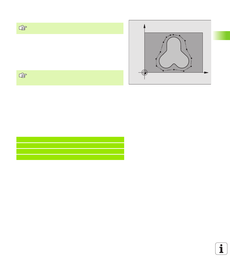
Defining the digitizing range in a specific shape (only available
with measuring touch probes)
The digitizing range is defined by a contour point table generated in the
Positioning with MDI mode of operation. You can either transfer the
individual points by teach-in programming or move the touch probe
around the model manually and have the TNC generate them
automatically (see figure at right).
U
U
U
U
PGM Name digitizing data
: Enter the name of the file in which the
TNC is to store the digitizing data.
U
U
U
U
TCH PROBE axis
: Enter the touch probe axis
U
U
U
U
PGM Name range data
: Enter the name of the point table in which you
have defined the range.
U
U
U
U
Min point TCH PROBE axis
: Lowest probe axis coordinate in the
DIGITIZING range.
U
U
U
U
Max point TCH PROBE axis
: Highest probe axis coordinate in the
DIGITIZING range.
U
U
U
U
Clearance height
: Position in probe axis at which the stylus cannot
collide with the model.
Example
Digitizing cycle 15 cannot be combined with digitizing
cycle 17 CONTOUR LINES.
In the screen menu for configuring the data interface, you
must enter the complete directory path in which the TNC
is to store the digitized data.
50 TCH PROBE 15.0 RANGE
51 TCH PROBE 15.1 PGM DIGIT: DATA
52 TCH PROBE 15.2 PGM RANGE: TAB1
53 TCH PROBE 15.3 MIN: +0 MAX: +10 HEIGHT: +100
X
Y